Novel material groove and stretching mold used for machining of novel material groove

A material trough, a new type of technology, applied in the field of machinery, can solve the problems of the material trough body processing, material consumption, unreasonable structural design, etc., and achieve the effect of reducing material consumption, avoiding material consumption problems, and reducing force and eccentric load.

Active Publication Date: 2017-10-03
SHANDONG JINXING STAINLESS STEEL TECH CO LTD
View PDF9 Cites 1 Cited by
  • Summary
  • Abstract
  • Description
  • Claims
  • Application Information

AI Technical Summary

Problems solved by technology

[0003] Some people also try to increase the height of the back panel and the left and right side panels by using the traditional stretching process, but because of unreasonable structural design or lack of matching processing molds, the main body of the trough cannot be processed by the stretching process. come out
[0004] Therefore, how to design a new type of trough that can be produced by stretch forming processing technology to solve the problem of material waste has become an urgent technical problem in the sow breeding industry.

Method used


Image

  • Novel material groove and stretching mold used for machining of novel material groove
  • Novel material groove and stretching mold used for machining of novel material groove
  • Novel material groove and stretching mold used for machining of novel material groove

Examples


Embodiment Construction

[0036] In order to clearly illustrate the technical features of the solution of the present invention, the solution will be described below through specific implementation modes.

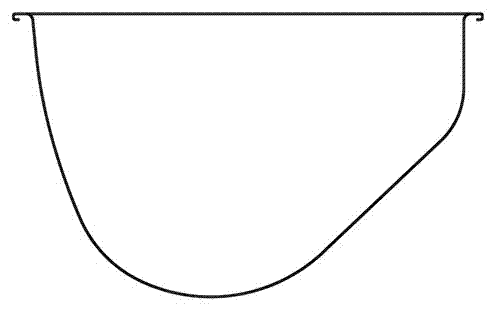
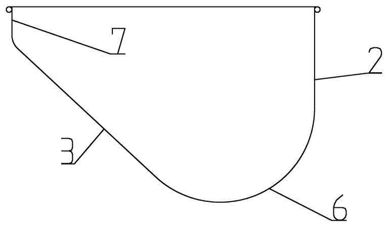
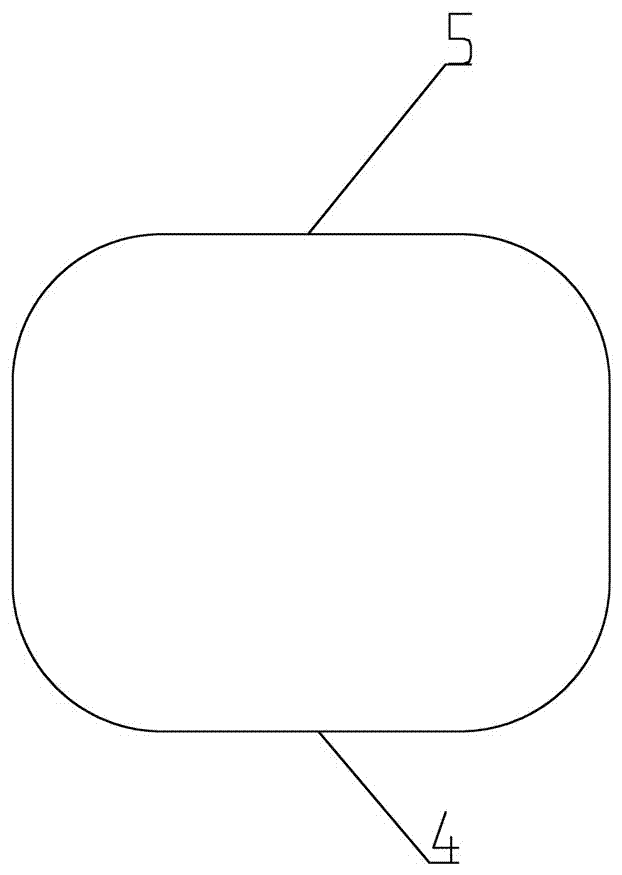
[0037] Such as Figure 2 to Figure 4 As shown in , a new trough includes a body and an installation part 1 fixed outside the body. The body includes a front plate 2, a back plate 3, a left side plate 4, a right side plate 5 and a bottom plate 6. The top of the back plate 3 is also connected with a folded plate 7, the front plate 2, the back plate 3, the left side plate 4, and the right side plate 5 are arc-shaped transitions and integrally formed with the bottom plate 6, and the bottom plate 6 is integrally formed. The front plate 2 and the back plate 3 are arc-shaped transition plates, and the folded plate 7 is integrally formed with the back plate 3, the left side plate 4 and the right side plate 5, and the front plate 2 and the back plate are integrally formed. The opening surrounded by the flap...


PUM


Abstract

The invention relates to a novel material groove which comprises a body and an installation machine part fixed to the outside of the body; the body comprises a front plate, a back plate, a left side plate, a right side plate and a bottom plate, and the top end of the back plate is further connected with a folded plate; the front plate, the back plate, the left side plate and the right side plate are all in arc transition with the bottom plate, and the front plate, the back plate, the left side plate, the right side plate and the bottom plate are integrally formed; the folded plate and the back plate as well as the left side plate and the right side plate are also integrally formed, and an opening defined by the front plate, the folded plate connected with the back plate, the left side plate and the right side plate is a round corner rectangle; in use, the included angle of the plane where the opening is located and the horizontal surface is 45 degrees, and the back plate is perpendicular to the horizontal surface; and the ratio of the height from the vertical surface where the highest point of the folded plate is located to the horizontal surface to the height from the vertical surface where the front plate is located to the horizontal surface is 3.5:1, the height of the vertical surface of the front plate is 144 mm, and on this basis, the invention further provides a stretching mold used for machining. The novel material groove has the beneficial effects that the appearance is aesthetic, the machining cost is relatively low, and materials are saved in use.

Description

technical field [0001] The invention relates to the field of machinery, in particular to a stainless steel trough used in the farming field, specifically a new type of trough and a stretching die used for its processing. Background technique [0002] At present, for the breeding industry, how to improve the utilization rate of feed is a very critical issue. A high feed utilization rate will reduce the cost of breeding. For the feeding of sows, the stainless steel trough used is currently the most primitive structure of the trough. figure 1 As shown in , the size of this trough is relatively small. A common size is 515mm in length, 380mm in width, and 230mm in depth. Due to the small force and unbalanced load on the front and back during processing, it can be processed by stretch forming technology. The height of the board and the side boards is low, so it is very easy for the sow to arch out the feed in the trough when eating, resulting in a great waste of feed. In order t...

Claims


Application Information

Patent Timeline
IPC IPC(8): B21D37/10B21D22/20B21D43/00B21D24/04A01K5/01
CPCA01K5/01B21D22/20B21D24/04B21D37/10B21D43/00
Inventor 徐永福
Owner SHANDONG JINXING STAINLESS STEEL TECH CO LTD
Why Eureka
Try Eureka