
Underwater low-power focusing and high-power flash switch control LED lamplight control apparatus and method

A technology for lighting control and LED lamp sockets, which is used in gas/waterproof devices, lighting devices, electroluminescent light sources, etc., can solve the problems of less flashing times, shortened effective working time, and high product cost, and achieves simplified heat dissipation design. , increase the battery life, the effect of low average power

Pending Publication Date: 2017-09-29
SHENZHEN YU MEI MING TECH CO LTD
View PDF7 Cites 2 Cited by
  • Summary
  • Abstract
  • Description
  • Claims
  • Application Information

AI Technical Summary

Problems solved by technology

The disadvantage of this method is that it can only emit light instantaneously, and cannot be used for focusing with continuous lighting, and because the device generally uses dry batteries, the number of flashes used is small and the service life is short
The other is LED high-power lighting auxiliary lighting, which is an auxiliary lighting method that achieves the ambient brightness required for shooting by continuously emitting light. Usually, LED lighting is always required to work under high-power conditions. Such work The effective working time is greatly shortened by this method, and this kind of high-power lamps generates a lot of heat and requires a larger volume for heat dissipation, so the product cost is high
Therefore, whether it is a flash light that uses gas pulse light or a technology that uses high-power LEDs as auxiliary lighting for photographing, there are shortcomings such as short effective use time, high equipment cost, and complicated operation.

Method used


Image

  • Underwater low-power focusing and high-power flash switch control LED lamplight control apparatus and method
  • Underwater low-power focusing and high-power flash switch control LED lamplight control apparatus and method
  • Underwater low-power focusing and high-power flash switch control LED lamplight control apparatus and method

Examples


Embodiment Construction

[0025] The following examples are further explanations and illustrations of the present invention, and do not constitute any limitation to the present invention.

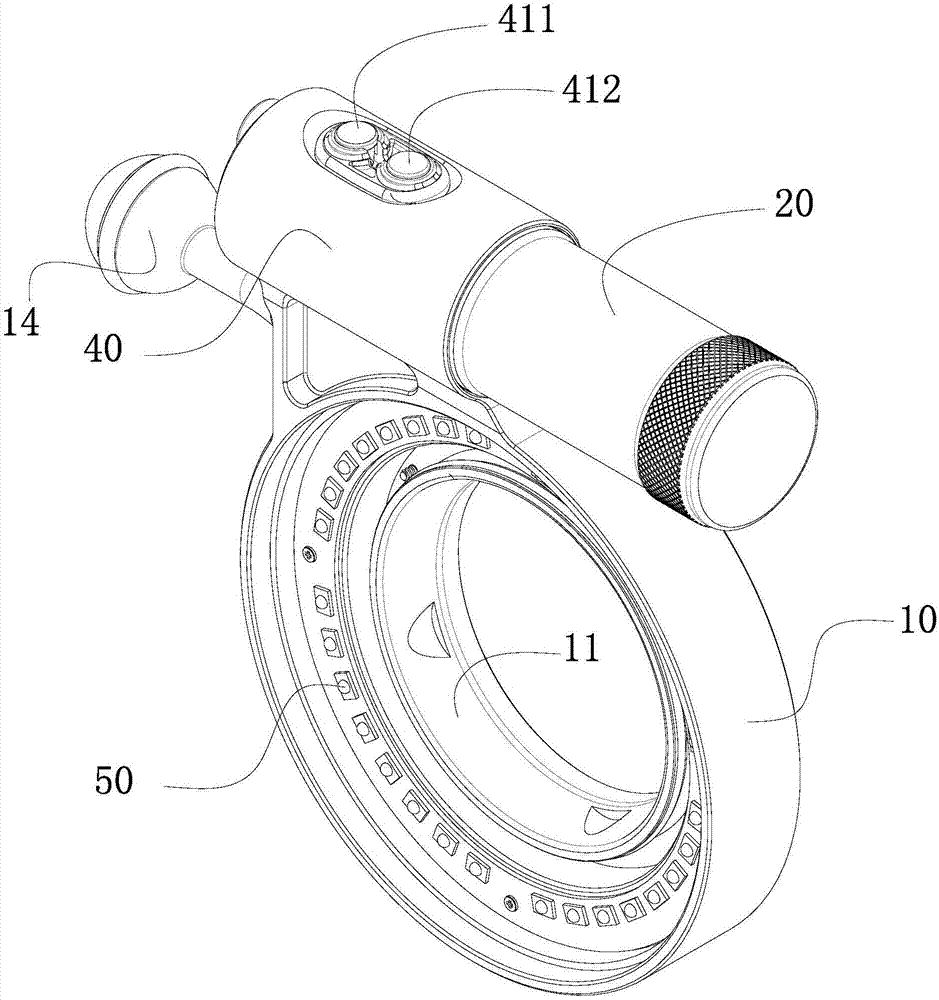
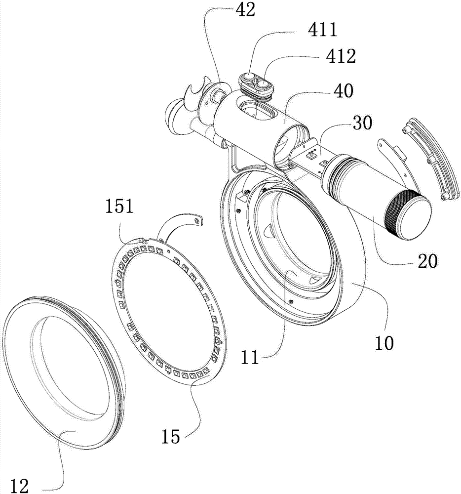
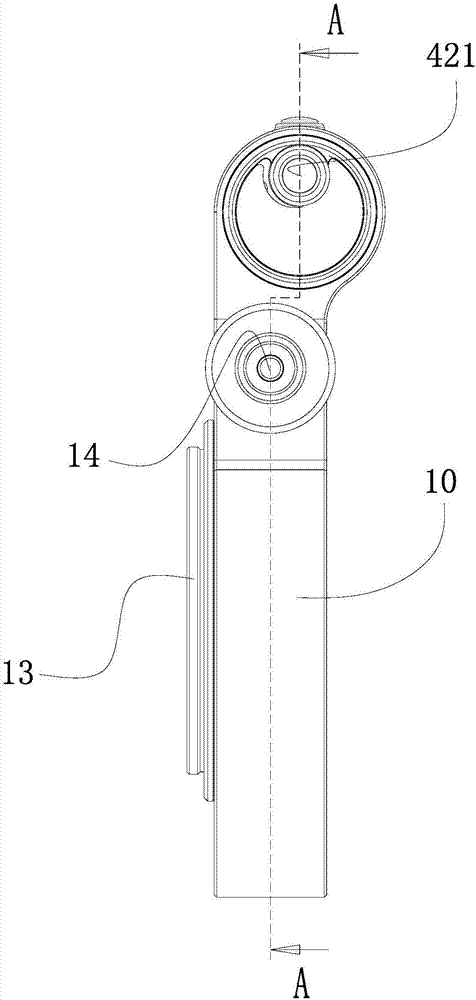
[0026] Such as Figure 1 to Figure 4 As shown, the underwater LED lighting control device of the present invention capable of automatically switching between low-power focusing and high-power flashing includes an LED lamp holder 10 , a battery compartment 20 , a main controller 30 , a cylindrical shell 40 and LED lamp beads 50 .

[0027] Such as Figure 1 to Figure 4 As shown, the LED lamp holder 10 is in the shape of a ring with an inner ring surface 11 in the center, and the inner diameter of the inner ring surface 11 matches the camera lens. On the ring surface of the front end of the LED lamp holder 10, there are a plurality of LED lamp beads 50 arranged at intervals along the circumferential direction of the ring surface, and the LED lamp beads 50 can be increased or decreased according to actual shooting need...


PUM


Abstract

Disclosed is an underwater low-power focusing and high-power flash switch control LED lamplight control apparatus. The apparatus is provided with a circular annular LED lamp holder; multiple LED lampbeads capable of displaying two different colors and with different luminance are arranged at intervals in the circumferential direction of the annular surface on the front side of the LED lamp holder; a battery cabin and a main controller connected to one side of the battery cabin are arranged on the upper part of the LED lamp holder; the main controller comprises a main control circuit and an optical signal conversion circuit connected therewith; the optical signal conversion circuit is provided with a photosensitive sensor PT; and the photosensitive sensor PT is connected with an optical fiber line led from the outer side of the main controller. By adoption of the apparatus, low-power weak light can assist focusing, and camera shooting light can be provided by high-power strong light; and in addition, the apparatus is low in average working power, long in endurance, good in heat dissipation effect and low in cost.

Description

【Technical field】 [0001] The invention relates to LED lighting control of underwater photography equipment, in particular to an LED lighting control device and method capable of automatically performing underwater low-power focusing and high-power flash switching control. 【Background technique】 [0002] At present, underwater photography has attracted many enthusiasts for its novelty, excitement and mystery. However, due to the complex underwater imaging environment and extremely low visibility, it is difficult to obtain clear imaging. Therefore, the selection and control of auxiliary lighting sources become the key to underwater photography. At present, the auxiliary lighting required for underwater photography generally adopts two methods. One is to use a xenon pulse discharge strobe to emit light, use the camera to trigger the flash, and cooperate with the camera to take pictures with supplementary light. The disadvantage of this method is that it can only emit light in...

Claims


Application Information

Patent Timeline
IPC IPC(8): G03B15/02G03B15/05H05B33/08F21V19/00F21V31/00F21Y115/10H05B44/00
CPCG03B15/02G03B15/05F21V19/003F21V31/005H05B45/00H05B45/325H05B45/10Y02B20/40
Inventor 刘大谋
Owner SHENZHEN YU MEI MING TECH CO LTD
Learn More