
Method and system for calculating transient junction temperature of IGBT (Insulated Gate Bipolar Translator) module

A junction temperature, transient technology, applied in the field of power electronics, can solve problems such as damage, inability to realize IGBT, and lack of methods for transient junction temperature

Active Publication Date: 2017-09-29
HUNAN UNIV
View PDF5 Cites 58 Cited by
  • Summary
  • Abstract
  • Description
  • Claims
  • Application Information

AI Technical Summary

Problems solved by technology

[0003] However, at present, there are a series of problems in the online extraction and detection of the operating junction temperature of the module. The optical non-contact measurement method can only obtain the temperature of the outer surface of the module at a specific moment, and the module package needs to be opened during the measurement, which is a destructive measurement method. , can not realize the online measurement of the chip junction temperature of the power device in the IGBT (Insulated Gate Bipolar Transistor, insulated gate bipolar transistor) module
The thermosensitive electric parameter method needs to design a special measurement circuit, the system control is difficult, and the measurement accuracy is low
The traditional electrothermal coupling model junction temperature measurement method has problems such as difficulty in obtaining module material characteristics and complex model structure when establishing a thermal resistance network model
[0004] In summary, the problem of the prior art is the lack of a method that can effectively reflect the transient junction temperature of each chip in the IGBT module

Method used


Image

  • Method and system for calculating transient junction temperature of IGBT (Insulated Gate Bipolar Translator) module
  • Method and system for calculating transient junction temperature of IGBT (Insulated Gate Bipolar Translator) module
  • Method and system for calculating transient junction temperature of IGBT (Insulated Gate Bipolar Translator) module

Examples


Embodiment 1

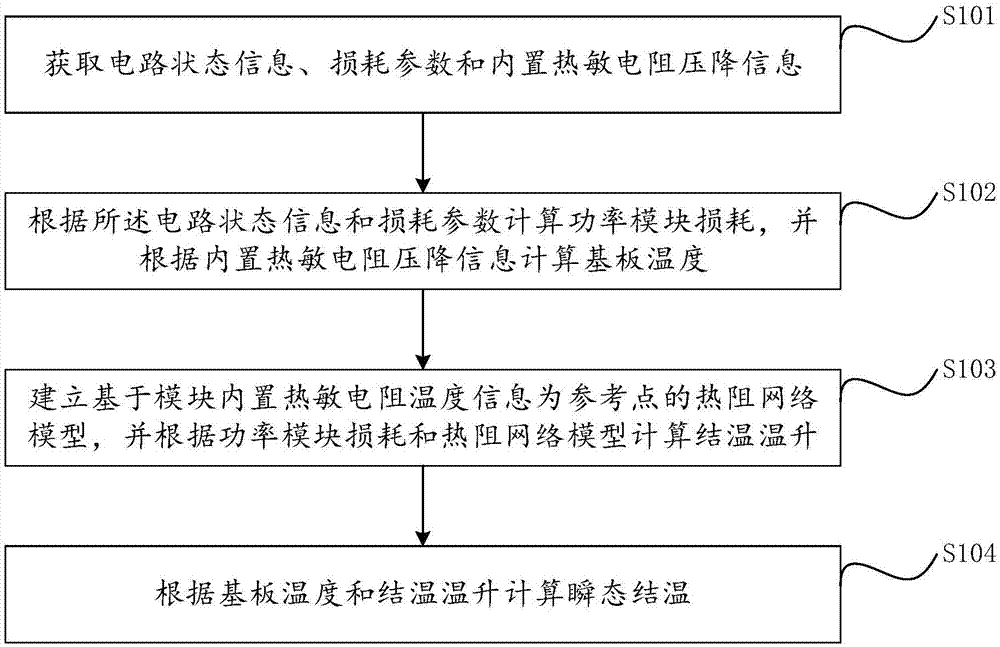
[0066] figure 1 It is a flowchart of a method for calculating the transient junction temperature of an IGBT module provided by Embodiment 1 of the present invention.

[0067] refer to figure 1 , the method of calculating the transient junction temperature of the IGBT module includes:

[0068] Step S101, obtaining circuit status information, loss parameters and built-in thermistor voltage drop information;

[0069] Step S102, calculating the loss of the power module according to the circuit state information and loss parameters, and calculating the substrate temperature according to the voltage drop information of the built-in thermistor;

[0070] Specifically, a switching device power loss model is established. The power loss model calculates the power module loss P by sampling electrical signals such as voltage, current, switch duty cycle, switching frequency, etc. (t).

[0071] Step S103, establishing a thermal resistance network model based on the temperature informatio...

Embodiment 2

[0111] Figure 5 A system structure diagram for calculating the transient junction temperature of an IGBT module provided by Embodiment 2 of the present invention.

[0112] refer to Figure 5 , the system for calculating the transient junction temperature of the IGBT module includes:

[0113] An acquisition unit 10, configured to acquire circuit state information, loss parameters and built-in thermistor voltage drop information;

[0114] The first calculation unit 20 is configured to calculate the power module loss according to the circuit state information and loss parameters, and calculate the substrate temperature according to the voltage drop information of the built-in thermistor;

[0115] The second calculation unit 30 is used to establish a thermal resistance network model based on the temperature information of the built-in thermistor in the module as a reference point, and calculate the junction temperature rise according to the power module loss and the thermal res...


PUM


Abstract

The invention provides a method and a system for calculating the transient junction temperature of an IGBT (Insulated Gate Bipolar Translator) module. The method comprises the steps of: acquiring circuit state information, loss parameter and internal thermistor voltage drop information; calculating power module loss according to the circuit state information and the loss parameter, and calculating substrate temperature according to the internal thermistor voltage drop information of the module; according to the temperature information provided by internal chips and the internal thermistor of the module as reference temperature, in consideration with thermal coupling between the internal chips of the power module at the same time, establishing a simpler IGBT module thermistor network model, and calculating a junction temperature rise according to the power module loss and the thermistor network model; and calculating the transient junction temperature according to the substrate temperature and the junction temperature rise, thus realizing on-line acquisition of the transient working junction temperature of the IGBT. By sufficiently utilizing the existing thermistor resource inside the power module, a junction temperature measurement system based on a power module electro-thermal coupling model is established, so that accurate power device junction temperature information is provided for security operation and health management of a converter system.

Description

technical field [0001] The invention relates to the technical field of power electronics, in particular to a method and system for online calculation of the transient junction temperature of an IGBT module. Background technique [0002] According to the research report on the reliability of power electronic systems, power devices are the components with the highest failure rate in the converter system, accounting for about 34%. Among various failure factors, about 55% of power electronic system failures are mainly induced by temperature factors. Therefore, in order to avoid severe performance degradation or even catastrophic damage of the power module, the maximum operating junction temperature and the junction temperature fluctuation of the power module should be closely monitored. Specifically, the thermal breakdown failure and thermal fatigue failure of the module are triggered by its highest operating junction temperature and junction temperature fluctuations, respectiv...

Claims


Application Information

Patent Timeline
IPC IPC(8): G01K7/22G01R31/26G06F17/50
CPCG01K7/22G01R31/2601G06F30/23
Inventor 刘平张星罗惠丹黄守道姜燕苏杭赵阳
Owner HUNAN UNIV
Learn More