


Quick Research
Generate reliable direction feasibility study reports for your R&D in just a few steps.

Technical Q&A
Discover and master advanced knowledge NOW. Basics, ideas, possibilities, all at once.

Find Solutions
As an expert in R&D theories, this can generate solutions to your technical problems instantly.

Evaluate Feasibility
Analyze your overall solution with one click, know your potential R&D risks in advance.

Monitor Landscape
Get weekly tech updates, stay abreast of the latest tech innovations and key insights.
Composite Floor Slab with Lattice Two-way Beam and Its Construction Method
A technology of combining floor slabs and construction methods, applied in the directions of slabs, joists, girders, etc., to achieve the effects of improving on-site construction efficiency, light weight, construction safety and quality stability
- Summary
- Abstract
- Description
- Claims
- Application Information
AI Technical Summary
Problems solved by technology
Method used
Image

Examples
Embodiment 1
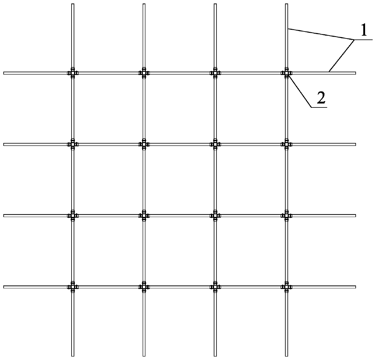
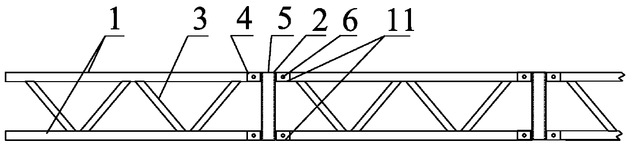
[0040] Such as figure 1 As shown, the trusses 9 are arranged in vertical and horizontal directions, and the trusses are segmented by two nodes, which can be made in a unified manner. The truss segments are connected to the node centerpieces of adjacent nodes. In this embodiment, the node centerpieces are vertical rectangles Tube 5, a typical rectangular tube is a square tube with the same length on each side of the cross-section, and the four outer sides of the square tube are connected with the truss section, such as figure 2 , the upper and lower chords of the four-section truss are fixedly connected to the upper and lower ends of the four sides of the square tube respectively.
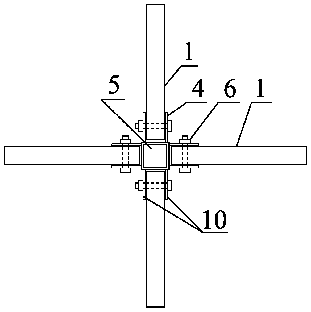
[0041] A specific fixed connection method such as figure 2 , image 3 As shown, connecting slots 4 are symmetrically welded at the connection between the upper end and the lower end of the four sides of the rectangular tube 5, and the connecting slot 4 is provided with a pair of parallel side pl...
Embodiment 2
[0045] Such as Figure 4 As shown, the truss 9 is connected to the node central piece from the vertical and horizontal directions, and the node central piece is a vertically welded gusset plate 7 ( Figure 6 ), the horizontal section of the gusset plate 7 is a centrally symmetrical cross, and the chords 1 of the upper and lower floors of the four-section truss are fixedly connected to the upper and lower ends of the four protruding wing plates of the gusset plate 7 respectively.
[0046] The chord 1 is formed by a pair of symmetrically arranged angle steels fixedly connected back to each other, each side wing plate of a pair of angle steels is on a horizontal plane, and the other side wing plate fixedly clamps the connecting plate 8, as Figure 6 As shown, in the upper chord, the horizontally arranged flaps are at the upper part, and the interconnected flaps are vertically arranged at the lower part of the upper chord; on the contrary, the horizontally arranged flaps are at th...
PUM
 Abstract
Description
Claims
Application Information
 - R&D Engineer
- R&D Manager
- IP Professional
- Industry Leading Data Capabilities
- Powerful AI technology
- Patent DNA Extraction
Browse by: Latest US Patents, China's latest patents, Technical Efficacy Thesaurus, Application Domain, Technology Topic, Popular Technical Reports.
© 2024 PatSnap. All rights reserved.Legal|Privacy policy|Modern Slavery Act Transparency Statement|Sitemap|About US| Contact US: help@patsnap.com