All-welded cable clamp

A cable clamp and arc-shaped technology, which is applied to bridge parts, bridges, buildings, etc., can solve the problems of increasing the difficulty of forming, cutting and welding, poor reliability, safety and practicability, and unfavorable forming efficiency. Achieve the effects of enhancing safety and practicality, stable and reliable stress structure, and improving molding effect and quality

Pending Publication Date: 2017-09-29
DEYANG TIANYUAN HEAVY IND
View PDF8 Cites 4 Cited by
  • Summary
  • Abstract
  • Description
  • Claims
  • Application Information

AI Technical Summary

Problems solved by technology

However, due to the irregularity of the circumferential structure of the cable clamp, it cannot be formed by the general processing of high-performance steel plates into an arc or cylindrical structure, and it also involves welding and forming of various combined connection structures , such as "a welded combined cable clamp" disclosed in Chinese patent literature (publication number: CN204112221, publication date: January 21, 2015), this technology is formed by a welded combined structure of steel plates, which can effectively and reliably overcome all The steel plate welded cable clamp with cast structure cable clamp disadvantages; however, its welded forming structure still has technical deficiencies, which is mainly reflected in the connecting ears (ie pressure-bearing platform) that are butted on each side of its arc-shaped plate (ie half-ring body) ) has multiple independent door-shaped pressure-bearing components, the number of these door-shaped pressure-bearing components is consistent with the number of bolt pairs required for the docking part, that is, if ten bolt pairs are required, then there must be ten penetration bolts The door-shaped pressure-bearing component of the pair, this cable clamp structure will not only increase the difficulty of forming (mainly the difficulty of cutting and welding the plates composed of the pressure-bearing component), but also is not conducive to the improvement of forming efficiency, which will increase the manufacturing cost and further What's more, the overall rigidity of the connecting ear composed of multiple independent door-shaped pressure-bearing components is poor, and the door-shaped pressure-bearing components on the same connecting ear cannot carry superhigh pressure evenly, stably and reliably. Strong locking force, easy to cause safety hazards, poor reliability, safety and practicability, needs to be improved urgently

Method used


Image

  • All-welded cable clamp
  • All-welded cable clamp
  • All-welded cable clamp

Examples


Embodiment 1

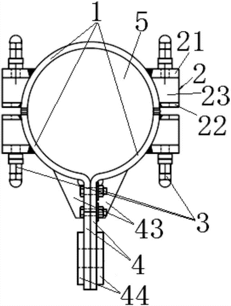
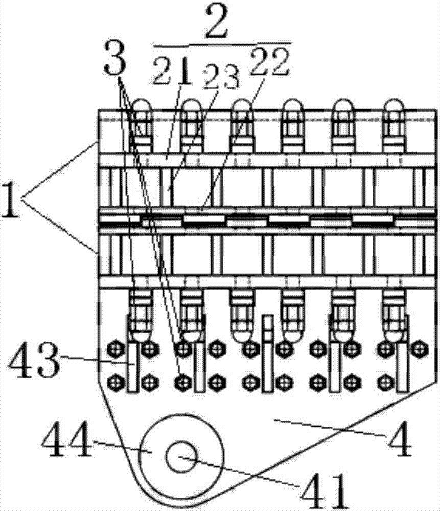
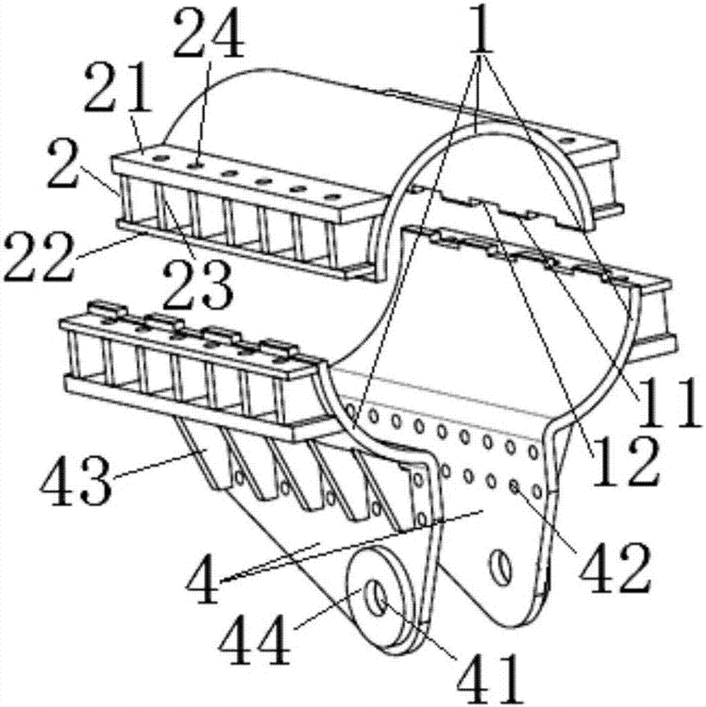
[0030] see Figure 1 to Figure 9As shown, the present invention has three arc-shaped plates 1 rolled or stamped with steel plates, wherein one is an arc-shaped plate 1 with a semi-circular structure, and two are arc-shaped plates 1 with ear plates respectively. These three arc-shaped plates 1 are sequentially combined and connected in the circumferential direction and surround the cable hole 5. Taking the outer circumference of the cable hole 5 as a benchmark, the three arc-shaped plates 1 are divided in a semi-circular structure arc-shaped plate 1 The arc length accounts for about 1 / 2 of the cable hole 5 peripheries, and the arc lengths of two arc-shaped plates with ear plates account for about 1 / 4 of the cable hole 5 respectively. Based on this, the above-mentioned three arc-shaped plates 1 have three combined joints when surrounding the cable hole 5, two of which are arc-shaped plates 1 with a semi-circular structure and two arc-shaped plates 1 with ear plates Between, one...

Embodiment 2

[0039] The invention has two arc-shaped plates rolled or stamped with steel plates, and the two arc-shaped plates are respectively provided with lug plates. These two arc-shaped plates are sequentially combined and connected in the circumferential direction to enclose the cable hole. Taking the outer circumference of the cable hole as the reference, the two arc-shaped plates are divided in such a way that their arc lengths account for about 1% of the outer circumference of the cable hole. / 2. Based on this, when the aforementioned two arc-shaped plates enclose the cable hole, there are two combined connection joints, one of which is the edge circumferential butt joint, and the other is the ear plate butt joint.

[0040] In the above combination connection, the non-lug side of the two arc-shaped plates is implemented in a manner of peripheral butt joint. When two adjacent arc-shaped plates (that is, two arc-shaped plates with ear plates) that are butted in the circumferential ...

Embodiment 3

[0048] The other content of this embodiment is the same as that of Embodiment 1, the difference is that: the arc-shaped plate of the semi-annular structure is divided into two, so that there are four arc-shaped plates surrounding the cable hole; the arc-shaped plate of the semi-annular structure After the form plate is divided into two, a joint part with peripheral butt joint is added, and the joint part also uses paired connection lugs to achieve butt joint, that is, the corresponding butt joint edges of the two arc-shaped plates after separation are respectively welded through type The integral connecting ear of the two arc-shaped plates matches the connecting ear of the corresponding butt edge.


PUM


Abstract

An all-welded cable clamp is provided with a plurality of arc-shaped plates formed by steel plates, wherein the arc-shaped plates are sequentially combined and connected in the peripheral direction to form a cable hole in a surrounding manner; edges of at least two arc-shaped plates are connected in the peripheral direction; connecting lugs formed by steel plates are respectively arranged on outer walls of the two arc-shaped plates of which the edges are connected in the peripheral direction; each connecting lug mainly comprises an outer pressure-bearing plate, an inner pressure-bearing plate and a plurality of supporting rib plates which are welded to the outer wall of the corresponding arc-shaped plate; each outer pressure-bearing plate and the corresponding inner pressure-bearing plate are elongated, are separated from each other in the peripheral direction of the corresponding arc-shaped plate, and are welded to the outer wall of the corresponding arc-shaped plate in the length direction of the arc-shaped plate; the welded position of each inner pressure-bearing plate is close to the peripheral connected edge of the corresponding arc-shaped plate; the supporting rib plates of each connecting lug are successively separated from one another in the length direction of the corresponding arc-shaped plate, are arranged on the outer wall of the corresponding arc-shaped plate, and are positioned between the corresponding outer pressure-bearing plate and the corresponding inner pressure-bearing plate; three sides of each supporting rib are welded with the corresponding outer pressure-bearing plate, the corresponding arc-shaped plate and the corresponding inner pressure-bearing plate; and a plurality of bolt holes which correspond in pairs are formed in parts, which are staggered from the corresponding supporting rib plates, of each outer pressure-bearing plate and each inner pressure bearing plate.

Description

technical field [0001] The invention relates to a cable clamp, a stressed member of a suspension bridge, in particular to a fully welded cable clamp. Background technique [0002] The cable clamp is an important force-bearing component that directly transfers the static and dynamic loads of the bridge deck to the main cable in the suspension bridge, and its forming quality directly affects the stability and safety of the suspension bridge. [0003] For a long time, the cable clips used in suspension bridges have basically all adopted full-cast structures. In order to ensure the stress strength and molding quality of cast-molded cable clips, it has very high technical requirements for casting molding, especially heat treatment with great technical difficulty. Casting defects are prone to occur during the casting process, such as pores, shrinkage cavities, Shrinkage, sand inclusions, cracks and other defects lead to low casting pass rate and molding efficiency of the cable cl...

Claims


Application Information

Patent Timeline
Patent Type & Authority Applications(China)
IPC IPC(8): E01D19/16
CPCE01D19/16
Inventor 黄安明陈远林陈龙
Owner DEYANG TIANYUAN HEAVY IND
Why Eureka
Try Eureka