
Device and method for automatically adjusting powder spreading amount of 3D printer

A 3D printer, automatic adjustment technology, applied in the field of 3D printing, can solve the problems of aggravated powder recovery task, forming termination, part forming size error, etc.

Active Publication Date: 2018-08-07
广州鑫研锦增材科技有限公司
View PDF4 Cites 0 Cited by
  • Summary
  • Abstract
  • Description
  • Claims
  • Application Information

AI Technical Summary

Problems solved by technology

If the amount of powder spread is too small, the powder spread in the powder spread area will be incomplete, which will cause the error of the forming size of the part. The formation is terminated due to powder, which seriously affects the stability of the high-energy beam selective melting process, and the formed parts are often defective or scrapped.
At present, the commonly used quantitative powder feeding method is an open-loop control system. The operator compensates and adjusts the powder amount according to the actual situation, and adopts the method of over-powder amount that is 2 to 4 times the actual powder amount required. The waste of powder is serious and the powder The amount of tasks during recycling, and it is not possible to adjust the amount of powder coating in real time according to the powder coating situation of the forming platform

Method used


Image

  • Device and method for automatically adjusting powder spreading amount of 3D printer
  • Device and method for automatically adjusting powder spreading amount of 3D printer
  • Device and method for automatically adjusting powder spreading amount of 3D printer

Examples


Embodiment Construction

[0053] In order to facilitate the understanding of the present invention, the present invention will be described more fully below with reference to the associated drawings. Preferred embodiments of the invention are shown in the accompanying drawings. However, the present invention can be embodied in many different forms and is not limited to the embodiments described herein. On the contrary, these embodiments are provided to make the understanding of the disclosure of the present invention more thorough and comprehensive.

[0054] It should be noted that when an element is referred to as being “fixed” to another element, it can be directly on the other element or there can also be an intervening element. When an element is referred to as being "connected to" another element, it can be directly connected to the other element or intervening elements may also be present.

[0055] Unless otherwise defined, all technical and scientific terms used herein have the same meaning as...


PUM


Abstract

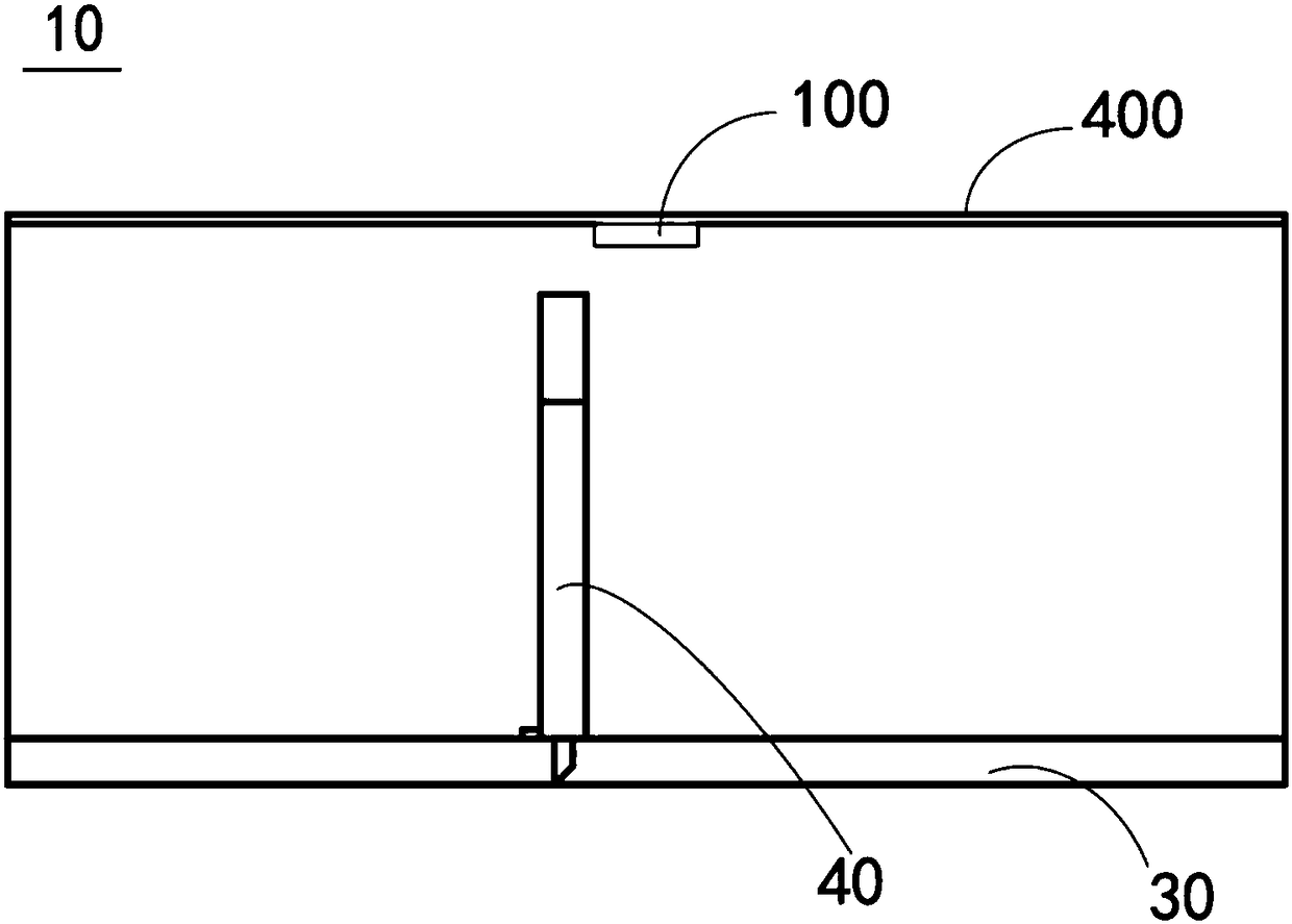
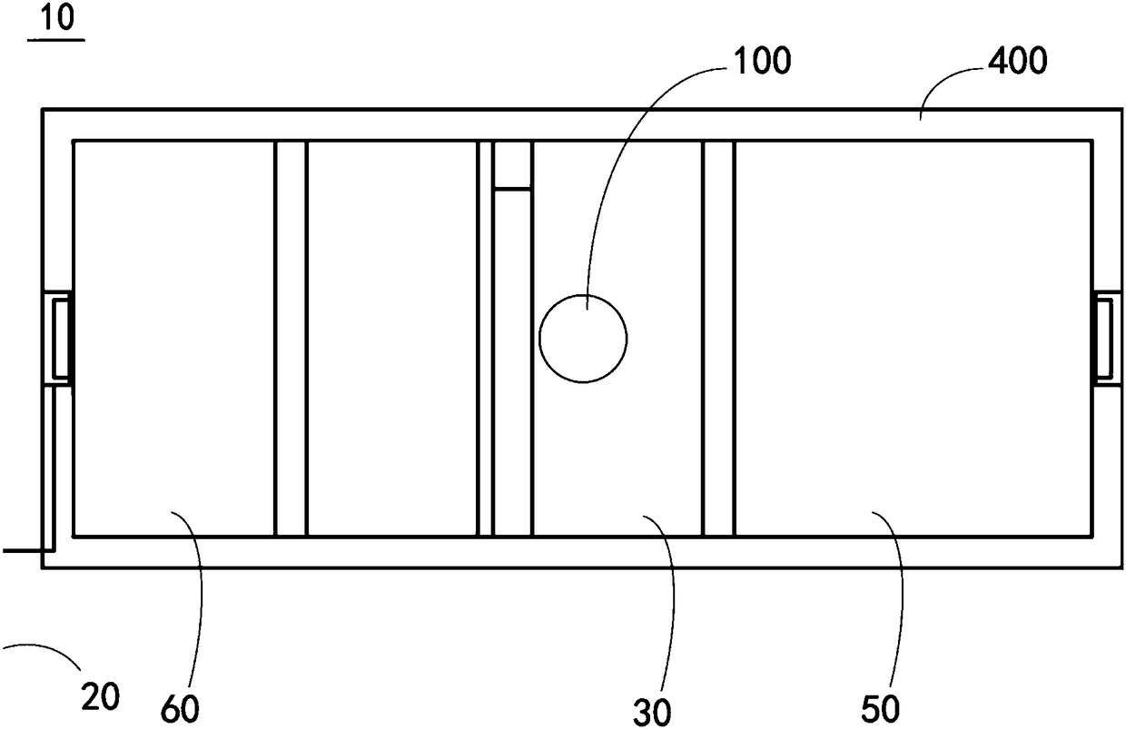
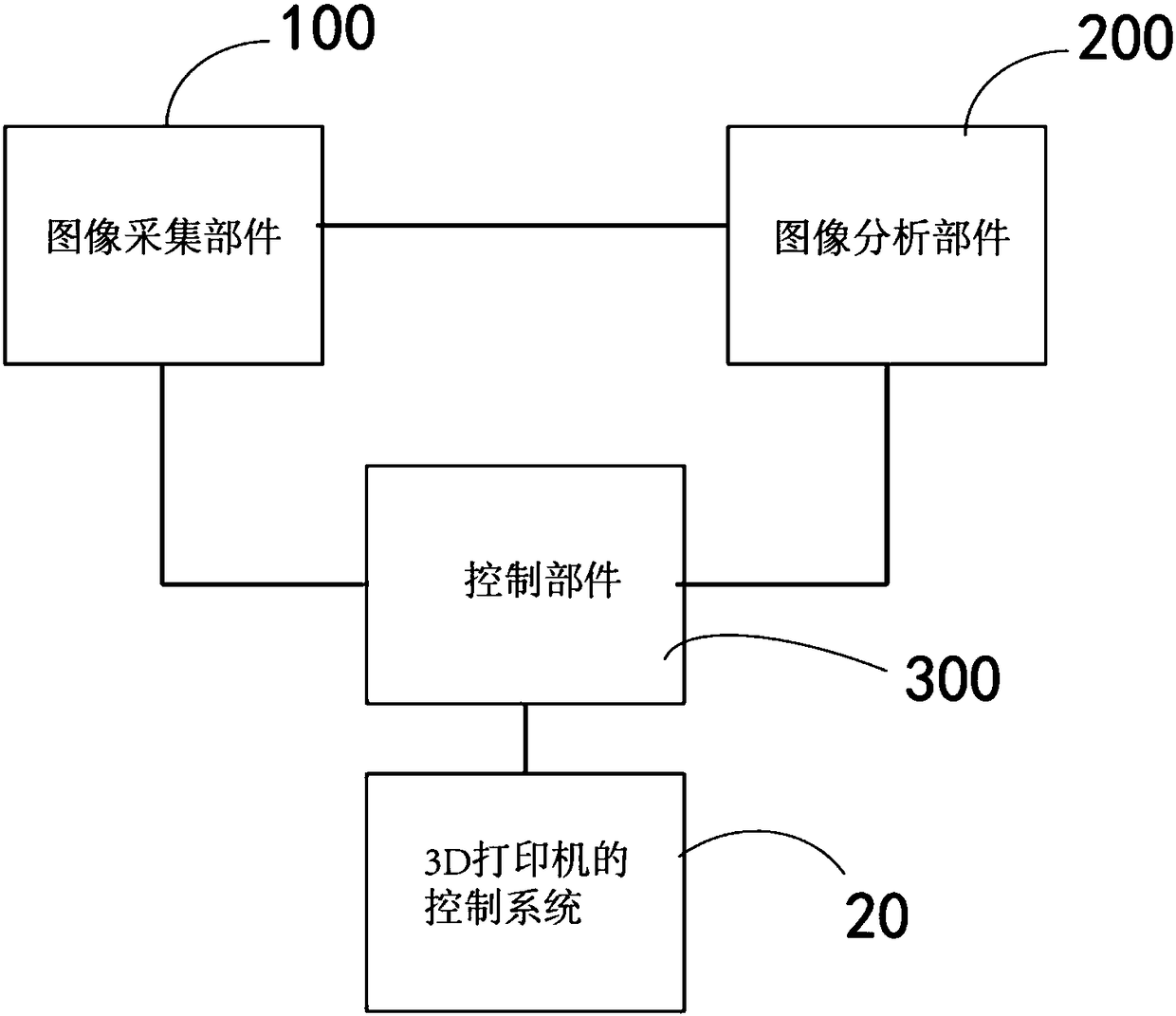
The invention discloses a device and a method for automatically adjusting the powder coating amount of a 3D printer. The device comprises an image collection component, an image processing component and a control component. The image collection component is used for collecting images of a forming baseplate in a forming cavity of the 3D printer after powder coating one time, and images of semi-finished products of parts to be printed and made by sintering after the powder coating. The image processing component is connected to the image collection component, and used for processing the images, collected by the image collection component, of the forming baseplate after the powder coating one time, and the images of the semi-finished products of the parts to be printed and made by sintering after the powder coating, so that the distance between the powder edges of the forming baseplate after the power coating one time and the edges of the semi-finished products of the parts to be printed is obtained, and the control component is used for outputting the optimal powder coating amount parameter of the 3D printer according to the distance. The control component can be used for adjusting the powder coating amount parameter according to the optimal powder coating amount parameter. The device for automatically adjusting the powder coating amount of the 3D printer is rational in design and low in cost.

Description

technical field [0001] The invention relates to the field of 3D printing, in particular to a device and a method for automatically adjusting the powder spreading amount of a 3D printer. Background technique [0002] Selected area laser sintering / melting technology is a newly developed direct 3D printing technology for metal parts. Its principle is to use a computer to layer the 3D CAD model and process the section information, and then input the section data into the 3D printer. The metal powder is laid layer by layer and the selected area of ​​the powder layer is melted by the high-energy beam laser. After all the cross-sections are melted and superimposed layer by layer, the three-dimensional solid parts of the designed structural shape are obtained. In the process of processing, after each layer is processed, the workbench is lowered by a certain distance, and the powder feeder sends out a certain amount of powder, which is then paved by the powder spreading mechanism, an...

Claims


Application Information

Patent Timeline
Patent Type & Authority Patents(China)
IPC IPC(8): B29C64/153B29C64/205B29C64/393B33Y30/00B33Y50/02
CPCB33Y30/00B33Y50/02
Inventor 佟鑫黄玉山
Owner 广州鑫研锦增材科技有限公司
Learn More