Steel beam attachment structure

A technology for joining structures and steel beams, which is applied to building components, building structures, buildings, etc., can solve the problems of complex production and combination of bending plates, not belonging to the transmission of torque, and quality reduction, so as to improve economic efficiency and construction performance , improve quality, and save steel processing costs

Active Publication Date: 2017-09-26
SAMSUNG C&T CORP +1
View PDF6 Cites 7 Cited by
  • Summary
  • Abstract
  • Description
  • Claims
  • Application Information

AI Technical Summary

Problems solved by technology

[0015] However, the manufacture and combination of the bent plates used for the web and beam joints of the described technology is very complicated.
[0016] In addition, the bolts of the web are only fixed by simply connecting adjacent parts, and do not belong to the structure of transmitting torque.
Therefore, there are problems of quality reduction and safety accidents caused by on-site welding work adjacent to the upper and lower flanges

Method used


Image

  • Steel beam attachment structure
  • Steel beam attachment structure
  • Steel beam attachment structure

Examples


Embodiment Construction

[0061] The present invention will be described in detail below with reference to the accompanying drawings and preferred embodiments.

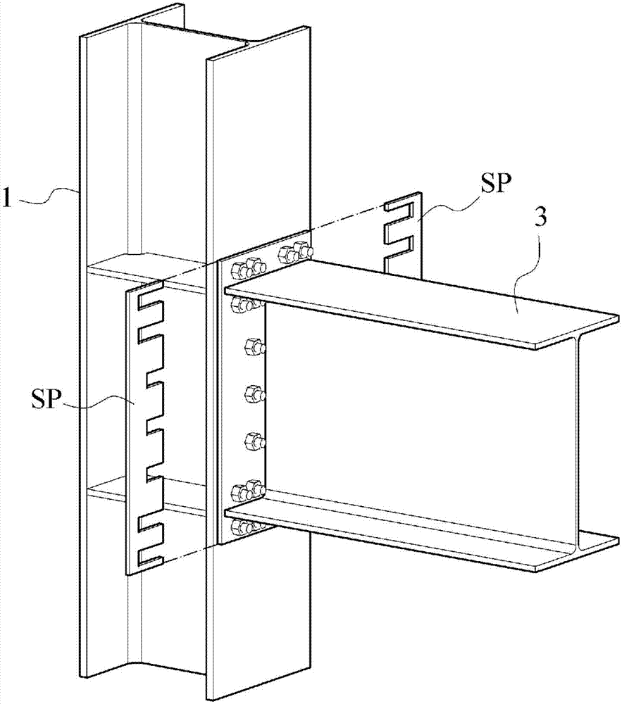
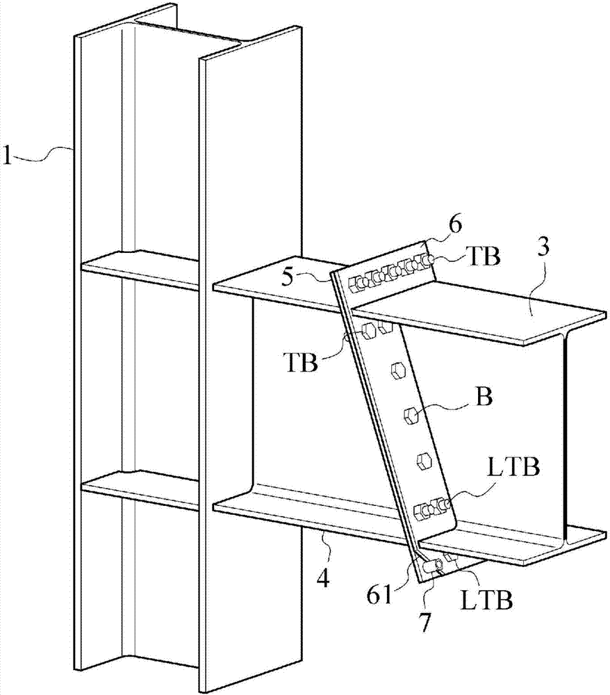
[0062] image 3 is a perspective view showing an embodiment of the steel beam joint structure of the present invention, Figure 4 is a perspective view illustrating a steel beam assembly method, Figure 5 is a perspective view showing an embodiment in which beam haunches have been incorporated.

[0063] The present invention relates to a steel beam joint structure for fixing a steel beam 3 on the side of a column 1 or girder 2 in conjunction with a bracket 4 on the side of a column 1 or girder 2 and joining the steel beam 3 to said bracket 4 steel beam joint structure.

[0064] Figure 3 to Figure 5 An embodiment in which the bracket 4 is combined to the side of the column 1 is shown, which will be described later Figure 11 to Figure 16 An embodiment in which the bracket 4 is coupled to the side of the girder 2 will be described.

[006...


PUM


Abstract

The present invention relates to a steel beam attachment structure for coupling a steel beam to the lateral side of a large beam or a pillar and, more specifically, to a steel beam attachment structure enabling a huge decrease in the number of bolts by means of effective transmission of shear force due to a simple structure of the attachment surface of a steel beam and a bracket. In a steel beam attachment structure, according to the present invention, a bracket is coupled and fixed to the lateral side of a large beam or a pillar and a steel beam is coupled to the bracket such that the steel beam is coupled to the lateral side of the large beam or the pillar. One end of the bracket is coupled to the lateral side of the large beam or the pillar, and the other end is inclined such that the lower part thereof forms an acute angle, wherein a first attachment plate is coupled to the inclined end part of the bracket such that a fixed length thereof protrudes from the upper end of the bracket. The lower part of one end of the steel beam is inclined at an obtuse angle so as to correspond to the other inclined end of the bracket, wherein a second attachment plate is coupled to the inclined end part of the steel beam such that a fixed length thereof protrudes from the upper end of the steel beam. The bracket and the steel beam comprise an upper flange and a lower flange, respectively, and a web for connecting the upper and lower flanges, wherein the first attachment plate and second attachment plate are coupled and mutually attached by means of tensioning bolts above and below the upper flange of the steel beam and the bracket.

Description

technical field [0001] The present invention relates to a steel beam joint structure in which a steel beam is joined to the side of a column or a girder. More specifically, it relates to a structure that effectively transmits shear force at the joint surface of a steel beam and a bracket with a simple structure, thereby greatly reducing the number of bolts Steel beam joint structure. Background technique [0002] The steel frame structure with columns, beams and other main structural components made of steel is suitable for high-rise structures and long-span structures because of the use of high-strength steel, and is more suitable for its advantages in earthquake resistance and excellent constructability. [0003] The columns or beams constituting the steel frame structure are generally factory-fabricated in advance according to the design dimensions according to the design stress, and the steel beams are bonded to the columns on site for construction. [0004] In the past...

Claims


Application Information

Patent Timeline
Patent Type & Authority Applications(China)
IPC IPC(8): E04B1/58
CPCE04B1/58E04B2001/2418E04B2001/2448E04B1/2403E04B2001/2415E04B2001/2457E04B2103/06E04F10/0607E04F10/0651E04F10/0666E04B1/388E04B2001/389E04B2001/2451
Inventor 李昌男
Owner SAMSUNG C&T CORP
Why Eureka
Try Eureka