Self pressure regulating type intelligent regulating valve

An intelligent adjustment and self-adjustment technology, applied in sliding valves, valve details, valve devices, etc., can solve the problems of unguaranteed valve life and high noise, and achieve the effect of using a wide range of differential pressure, reducing noise, and reducing cavitation.

Active Publication Date: 2017-09-26
SUZHOU DELAN ENERGY TECH
View PDF9 Cites 5 Cited by
  • Summary
  • Abstract
  • Description
  • Claims
  • Application Information

AI Technical Summary

Problems solved by technology

Control valves are generally designed with different performances according to actual working conditions to adapt to different working conditions. For example, the design is suitable for valves that require large flow coefficients, valves that require low noise, and valves that require long life. Due to different performance There are mutual constraints between them. When the flow coefficient is large, the general noise will be very large, and the life of the valve cannot be guaranteed. Therefore, it is difficult for conventional control valves to have the above-mentioned performances at the same time to adapt to the above-mentioned various working conditions. Even a full-featured regulating valve is difficult to meet all requirements

Method used


Image

  • Self pressure regulating type intelligent regulating valve
  • Self pressure regulating type intelligent regulating valve
  • Self pressure regulating type intelligent regulating valve

Examples


Embodiment Construction

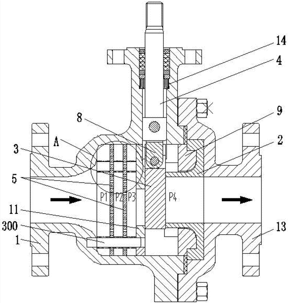
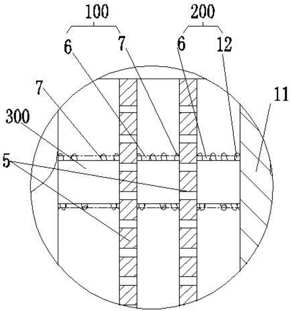
[0028] The present invention will be further described in conjunction with accompanying drawing and embodiment:

[0029] see Figure 1 to Figure 7 , as shown in the legend, a self-regulating intelligent regulating valve, including a valve body 1, a valve seat 2, a valve plate 3 and a valve stem 4, the valve body 1 is provided with a flow channel, and the valve seat 2 is located in the flow channel , the valve plate 3 cooperates with the valve seat 2 to form the on-off component of the flow channel, and the valve rod 4 drives the valve plate 3 to perform opening and closing movements respectively to open and close the flow channel respectively. The flow channel pressure regulating assembly on the fluid input side, the flow channel pressure regulating assembly includes at least two orifice plates 5, each orifice plate 5 is provided with a first elastic member 6 that drives it to reset, and the elastic force direction of the first elastic member 6 Opposite to the direction of fl...


PUM


Abstract

The invention discloses a self pressure regulating type intelligent regulating valve which comprises a valve body, a valve seat, a valve plate and a valve rod. A runner is arranged on the valve body. The valve seat is arranged in the runner. The valve plate and the valve seat cooperate so as to form a runner on-off assembly. The valve plate is driven by the valve rod. A runner pressure regulating assembly located on the fluid input side of the runner on-off assembly is further arranged in the runner. The runner pressure regulating assembly comprises at least two pore plates. Each pore plate is provided with a first elastic component driving the pore plate to reset. The elastic force direction of each first elastic component is opposite to the fluid flowing direction. Through the arrangement of the at least two pore plates and the first elastic components, when the flow coefficient is large, flow resistance is increased, and the pressure difference of the two sides of the positions of the valve plate and the valve seat is far smaller than that of the two sides of the positions of a valve plate and a valve seat of a traditional valve; the performance of the large flow coefficient is achieved, and meanwhile cavitation is reduced; meanwhile, noise can be lowered, high pressure difference vibration can be eliminated, operation force can be reduced, and the service life of the regulating valve can be prolonged; and meanwhile the valve structure is compact, and occupied mounting space is small.

Description

technical field [0001] The invention relates to the field of valves, in particular to a self-regulating intelligent regulating valve. Background technique [0002] Control valve, also known as control valve, in the field of industrial automation process control, is the final control element that changes the process parameters such as medium flow, pressure, temperature, liquid level, etc. by means of power operation by receiving the control signal output by the adjustment control unit. Control valves are generally designed with different performances according to actual working conditions to adapt to different working conditions. For example, the design is suitable for valves that require large flow coefficients, valves that require low noise, and valves that require long life. Due to different performance There are mutual constraints between them. When the flow coefficient is large, the general noise will be very large, and the life of the valve cannot be guaranteed. Therefo...

Claims


Application Information

Patent Timeline
Patent Type & Authority Applications(China)
IPC IPC(8): F16K3/02F16K3/18F16K3/32F16K47/02
CPCF16K3/0209F16K3/0272F16K3/188F16K3/32F16K47/02
Inventor 戚茂波沈杰
Owner SUZHOU DELAN ENERGY TECH
Why Eureka
Try Eureka