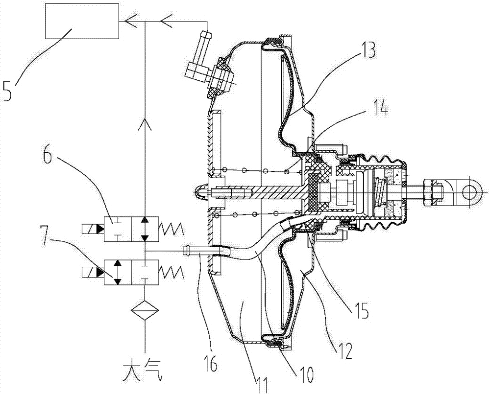
Automobile hydraulic brake system
A hydraulic braking and automotive technology, applied in the direction of brakes, brake transmissions, vehicle components, etc., can solve the problem that the system can only be controlled manually
- Summary
- Abstract
- Description
- Claims
- Application Information
AI Technical Summary
Problems solved by technology
Method used
Image
Examples
Embodiment Construction
[0027] In order to enable those skilled in the art to better understand the technical solution of the present invention, the present invention will be described in detail below in conjunction with the accompanying drawings and specific embodiments.
[0028] like figure 1 and figure 2 Shown, the embodiment of the present invention discloses a kind of automobile hydraulic braking system for automobile, figure 1 It is a structural schematic diagram of the automobile hydraulic braking system in the present invention, figure 2 It is an enlarged schematic diagram of the internal structure of the vacuum booster of the automobile hydraulic braking system in the present invention. The marks in are: 1-vacuum booster; 10-hose; 11-front chamber; 12-rear chamber; 13-diaphragm; 14-return spring; 15-vacuum valve port; Brake master cylinder; 3-ABS pump; 4-brake wheel cylinder; 5-vacuum source; 6-normally open solenoid valve; 7-normally closed solenoid valve; 8-controller; 9-pressure sens...
PUM
 Abstract
Description
Claims
Application Information
 - R&D Engineer
- R&D Manager
- IP Professional
- Industry Leading Data Capabilities
- Powerful AI technology
- Patent DNA Extraction
Browse by: Latest US Patents, China's latest patents, Technical Efficacy Thesaurus, Application Domain, Technology Topic, Popular Technical Reports.
© 2024 PatSnap. All rights reserved.Legal|Privacy policy|Modern Slavery Act Transparency Statement|Sitemap|About US| Contact US: help@patsnap.com


