Wide-beam and high-gain antenna

A high-gain antenna and wide-beam technology, which is applied in the direction of antenna, antenna coupling, antenna grounding switch structure connection, etc., can solve the problems that cannot meet the requirements of wave width and the effect of wave width broadening is limited, and achieve clear principle, optimized position, and realization simple effect

Pending Publication Date: 2017-09-22
TONGYU COMM INC
View PDF5 Cites 5 Cited by
  • Summary
  • Abstract
  • Description
  • Claims
  • Application Information

AI Technical Summary

Problems solved by technology

However, the above-mentioned method has a limited effect on broadening the wave width, and still cannot meet the wave width requirements of more than 90° in the entire band.

Method used


Image

  • Wide-beam and high-gain antenna
  • Wide-beam and high-gain antenna
  • Wide-beam and high-gain antenna

Examples


Embodiment Construction

[0056] The preferred embodiments of the invention patent are given below in conjunction with the accompanying drawings to describe the technical solution of the present invention in detail. Here, the present invention will be described in detail with reference to the accompanying drawings. It should be noted that the preferred implementation examples described here are only used to illustrate and explain the present invention, and are not used to limit or limit the present invention.

[0057] see Figure 1-16 , the design method of the wide-beam high-gain antenna comprises the following steps:

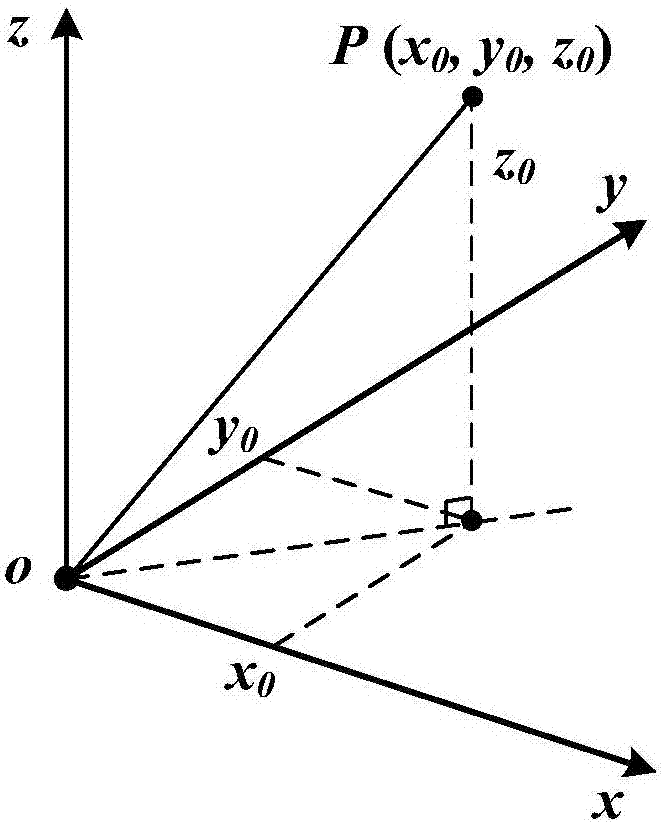
[0058] Step 1, establish a space Cartesian coordinate system, see figure 1 ;

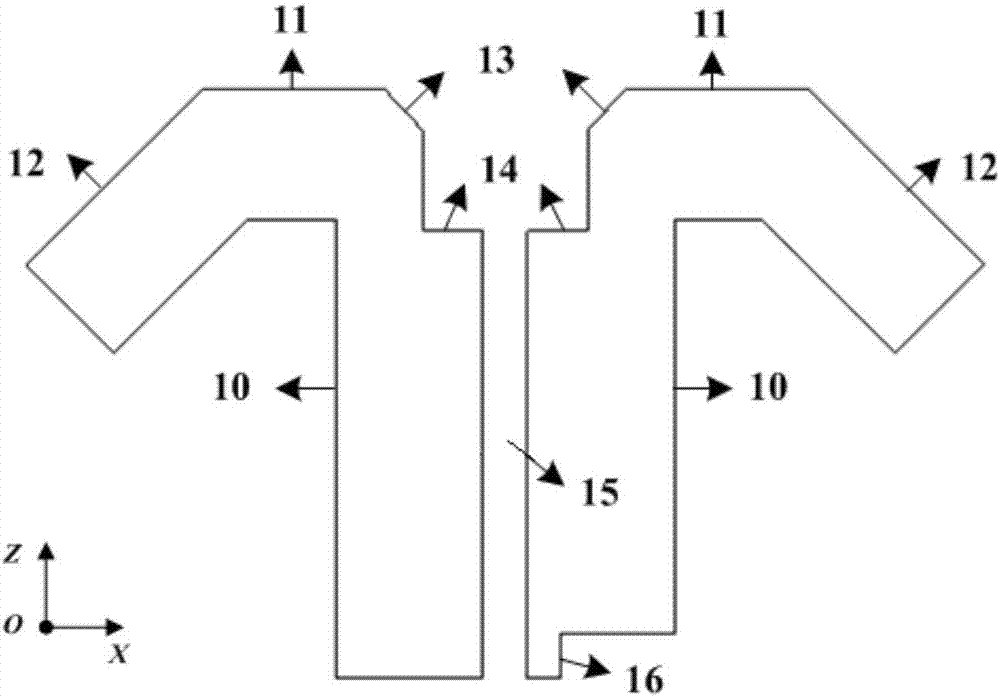
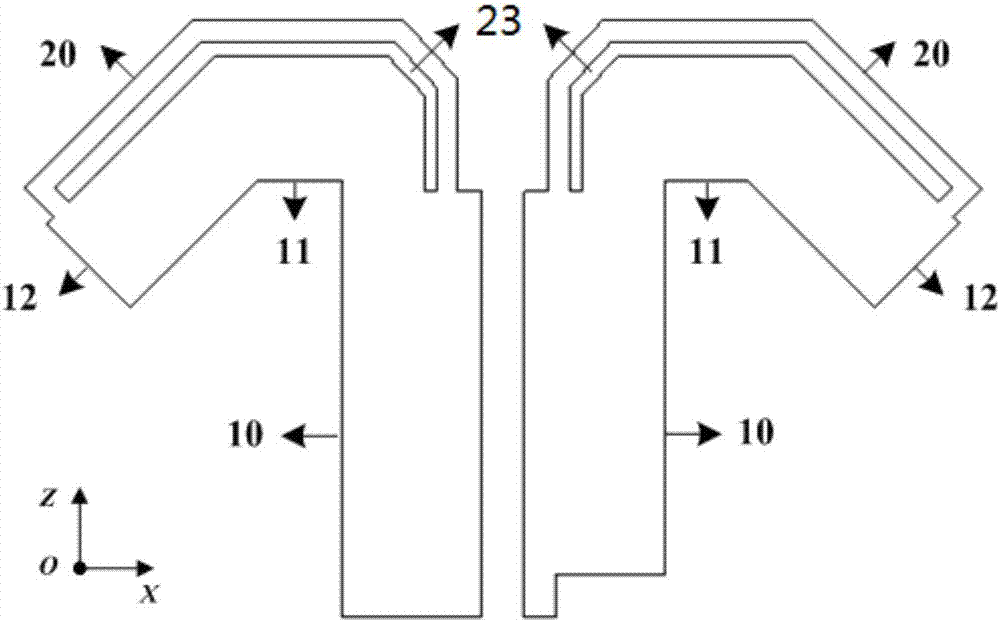
[0059] Step 2, constructing a drooping broadband oscillator. First, on the XOZ plane, build an inverted L-shaped sheet along the +Z axis direction, the bottom of which is a vertical section 10, the top is a horizontal section 11, and its end is turned downward into a bent section 12; the vertical section...


PUM


Abstract

The invention discloses a wide-beam and high-gain antenna, comprising a cross oscillator pair arranged on a reflector and formed by a plurality of arrays, wherein the cross oscillator pair comprises pendulous wideband oscillators printed on two dielectric substrates respectively; the two pendulous wideband oscillators are cross, two arms of the oscillator are symmetric inverse L-shaped sheets with each including a vertical section and a horizontal extended section at the top of the vertical section, and the tail end of the horizontal extended section is a downward bent section; a parasitic unit is arranged on the upper side of the oscillator arm, a microstrip line is arranged on the other side of each of the two dielectric substrates, and the reflector is used for dual-polarized feed. The parasitic units are arranged on the upper side of the oscillator arms, thus realizing wide beams and good matching of single PCB (Printed Circuit Board) cross oscillators; and the wide-beam wideband PCB cross oscillator arrays obtain the characteristics of dual polarization, horizontal wide beams and high-gain radiation. The method is simple to implement, low in cost and suitable for batch production, and is applicable and effective for design and improvement of conventional wideband and high-gain oscillator antennas.

Description

【Technical field】 [0001] The invention relates to a mobile communication base station antenna device and technology, in particular to a wide-beam high-gain antenna and its technology. 【Background technique】 [0002] With the continuous increase of network deployment density, mobile communication has basically achieved wide-area continuous coverage of signals. However, limited by the operating frequency band and coverage area, it is difficult for macro cells to meet the requirements of high data transmission rate and large system capacity. In contrast, the 5.8G frequency band has wide bandwidth, large capacity, good propagation characteristics, and small antenna size, which is very suitable for local high-speed data services with dense users. This type of base station antenna needs to have the characteristics of large bandwidth (4.97-5.85GHz, BW=16.27%), high gain and wide (horizontal) wave width, so as to cover a large area and serve more users, so as to obtain good coverag...

Claims


Application Information

Patent Timeline
IPC IPC(8): H01Q1/36H01Q1/38H01Q15/14H01Q13/08H01Q1/52H01Q1/50
CPCH01Q1/36H01Q1/38H01Q1/50H01Q1/52H01Q13/08H01Q15/14Y02D30/70
Inventor 李道铁吴中林刘木林
Owner TONGYU COMM INC
Why Eureka
Try Eureka