Stop type handle automatic restoration and idling device

A technology of automatic reset and idling device, which is applied in the field of anti-theft locks, can solve the problems that the automatic reset feature of the handle is not described at the same time, the automatic reset device fails, and the key cannot be pulled out, etc., to meet the convenience of the product, the structure is simple, and the satisfaction safety effect

Active Publication Date: 2017-09-22
BEIHUA UNIV
View PDF13 Cites 31 Cited by
  • Summary
  • Abstract
  • Description
  • Claims
  • Application Information

AI Technical Summary

Problems solved by technology

Among them, all the above-mentioned patent applications do not mention the automatic reset of the handle. The actual operation method and existing problems are: after the handle is pressed down to unlock, the handle needs to be manually rotated to reset to a near-horizontal position, otherwise the key cannot be pulled out; After the anti-lift handle is locked, it is necessary to manually rotate the handle to reset. Although it is very light, if it is not reset, the handle will stop in an upward direction, which will affect the appearance
In this case, if only the automatic reset technology in the forward and reverse directions of the ordinary handle is used, the automatic reset device will fail after the handle is idling.
In addition, there are also patented products in the prior art that provide idling handles, such as "Overload Protector for New Intelligent Anti-theft Lock" (Patent No. 2015206788831). An overload protector is installed outside the lock body, but it is only limited to handles that can be idling. The automatic reset feature of the handle is not described at the same time, so the above-mentioned eight patent applications and other prior art do not address and solve the problem that the handle can be automatically reset in both forward and reverse directions and can also idle

Method used


Image

  • Stop type handle automatic restoration and idling device
  • Stop type handle automatic restoration and idling device
  • Stop type handle automatic restoration and idling device

Examples


Embodiment Construction

[0031] Combine below Figure 1 to Figure 15 The present invention is further described.

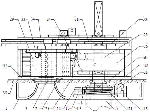
[0032] Such as figure 1 The overall assembly diagram of the lock shown is a technical solution in which the device of the present invention is used in conjunction with an anti-theft lock. The anti-theft lock in this solution is the product corresponding to the eight patents mentioned in the background technology. Wherein, the lock core group 29 and the cam mechanism are all installed between the anti-skid plate 32 and the back plate 33 of the lock body, the transmission mechanism of the lockset is located between the back plate 33 and the buckle cover 34, and the lock bolt and the dead bolt are positioned at the buckle cover 34. outside of the door (using an external hanging type movable connection method, not shown in the figure), the entire lock body is installed inside the door leaf, only the key opening 3 is exposed on the door leaf outer panel 35, and the outer end of the camshaft 2...


PUM


Abstract

The invention provides a stop type handle automatic restoration and idling device, and relates to the field of anti-theft locks. A normal handle bi-directional automatic reset mechanism is arranged on a bottom plate first, and the bottom plate is locked by inserting a bayonet pin into a slot of the bottom plate, wherein the bayonet pin is arranged on a swinging locking plate, the handle can reset automatically when being not rotated forwards or reversely by a certain angle; when the certain angle is exceeded, the locking plate is pushed by cavels of a driving wheel to swing, wherein the driving wheel is synchronously rotated with the handle, the bayonet pin is pulled out from the slot, lock of the bottom plate is relieved and the handle can idle; and after the handle rotates a circle, the bayonet pin is inserted into the slot again and the automatic reset function of the handle is recovered. The stop type handle automatic restoration and idling device is applicable to a lockset with an overload protecting device in the lock body, that is, the handle can reset automatically and is convenient to operate; the handle further can idle and used for prevent damaging and stealing the lockset.

Description

technical field [0001] The invention relates to the field of anti-theft locks, in particular to a stop type handle automatic reset and idling device. Background technique [0002] In the prior art, "lock core fixed cross mechanical anti-theft lock" (patent No. ZL201410020215.X), "a double-insert anti-theft door" (patent No. ZL201610068454.1), "double-insert anti-theft door and external lock Closing device" (Patent No. ZL201610129609.8), "A digital code, single key combination kit" (Patent No. ZL201610067763.7), "A profiling device for key matching machine" (Patent No. ZL201610068057.4), "Cylinder fixed cross mechanical anti-theft lock matching with fingerprint lock" (application number 201610990489.0), "a cam mechanism for fingerprint lock" (application number 201611045195.7) and "resetting mechanism for lock cylinder fixed cross mechanical anti-theft lock" ( Application No. 201710193748.1) and other eight invention patent applications, all of which have special structures ...

Claims


Application Information

Patent Timeline
IPC IPC(8): E05B15/00E05B3/08
CPCE05B3/08E05B15/0033E05B15/004
Inventor 吕雪寒张校诚
Owner BEIHUA UNIV
Why Eureka
Try Eureka