
Belt conveyor monitoring system based on Ethernet

A belt conveyor and monitoring system technology, applied in the direction of conveyor control devices, conveyors, conveyor objects, etc., can solve the problem of inability to realize loudspeaker broadcasting and voice alarm, and inability to realize frequency conversion and speed regulation based on coal flow, monitoring system Problems such as vibration cannot be monitored in real time to achieve a good human-computer interaction interface, convenient function expansion and modification, and enhanced system stability and reliability

Pending Publication Date: 2017-09-22
TIANJIN POLYTECHNIC UNIV +1
View PDF11 Cites 14 Cited by
  • Summary
  • Abstract
  • Description
  • Claims
  • Application Information

AI Technical Summary

Problems solved by technology

On the one hand, in terms of function, the detection function is not complete, the existing monitoring system cannot monitor vibration and motor current in real time, and the reliability of the detection data is poor, and the detection equipment is prone to failure; the control function can only realize the start and stop of the motor or soft start control, and cannot realize The coal flow is controlled by frequency conversion; the lack of video monitoring probes makes it impossible to monitor the key parts of the belt conveyor; the telephone terminals are connected by bus or audio lines, and the voice data is transmitted by analog signals, which requires separate wiring for the telephone , only simple fixed-point communication can be realized, and the voice call is half-duplex communication, and the functions of loudspeaker broadcasting and voice alarm cannot be realized
On the other hand, in terms of structure, the current belt conveyor monitoring system generally adopts the communication method in the form of a bus. The number of stations is also limited, and the system's functional scalability is poor

Method used


Image

  • Belt conveyor monitoring system based on Ethernet
  • Belt conveyor monitoring system based on Ethernet
  • Belt conveyor monitoring system based on Ethernet

Examples


Embodiment Construction

[0033] The present invention will be further described below in conjunction with accompanying drawing.

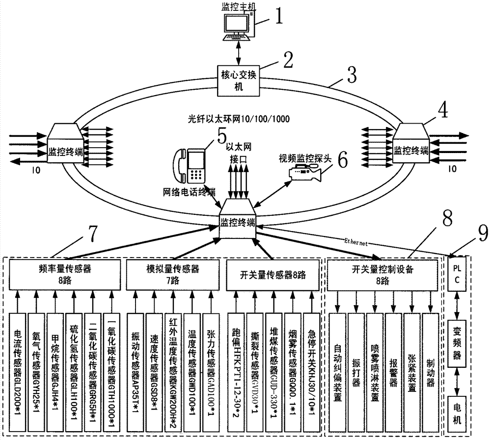
[0034] figure 1 Among them, 1. Monitoring host; 2. Core switch; 3. Optical fiber communication ring network; 4. Monitoring terminal; 5. Internet phone terminal; 6. Video monitoring probe; Motor frequency conversion control device.

[0035] figure 2 Middle, 7-1, current sensor; 7-2, oxygen sensor; 7-3, methane sensor; 7-4, hydrogen sulfide sensor; 7-5, carbon dioxide sensor; 7-6, carbon monoxide sensor; 7-7, vibration Sensor; 7-8, speed sensor; 7-9, infrared temperature sensor; 7-10, temperature sensor; 7-11, tension sensor; 7-12, deviation sensor; 7-13, tear sensor; 7-14 , Heap coal sensor; 7-15, smoke sensor; 7-16, emergency stop switch.

[0036] According to the accompanying drawings, the Ethernet-based belt conveyor monitoring system designed by the present invention consists of: monitoring host 1; core switch 2; optical fiber communication ring network 3; monitorin...


PUM


Abstract

The invention discloses a belt conveyor monitoring system based on the Ethernet. The belt conveyor monitoring system based on the Ethernet is characterized by comprising a monitoring host, a monitoring terminal, an optical fiber communication ring network, a series sensor, a switching value control device, a motor frequency conversion control device, a video monitoring probe and an internet telephone terminal; the monitoring host is a monitoring and control center of the belt conveyor monitoring system; the monitoring terminal completes collection of state information and field environment information of a belt conveyor; the optical fiber communication ring network is a double-ring network; the series sensor is arranged along a conveying belt and is used for detecting the environment information of the conveying belt and monitoring the work state of the conveying belt in real time; and the switching value control device gives out an alarm when the belt conveyor breaks down or running state problems are found and controls corresponding equipment to act or be shut down. The motor frequency conversion control device, the video monitoring probe and the network telephone terminal achieve corresponding functions. A comprehensive monitoring method is provided for monitoring of the belt conveyor.

Description

technical field [0001] The invention belongs to the technical field of mining equipment fault monitoring and control, and in particular relates to an Ethernet-based belt conveyor monitoring system. Background technique [0002] Belt conveyor, also known as belt conveyor or belt conveyor, is a friction-driven machine that transports materials in a continuous manner. It is mainly composed of frame, conveyor belt, idler roller, roller, tensioning device, transmission device, etc. At present, the belt conveyor is the most widely used continuous transportation equipment in coal mine underground and surface production systems. It has strong transportation capacity, small working resistance, low power consumption, long transportation distance, long service life, low noise, safety and reliability, etc. advantage. With the emergence of high-yield and high-efficiency mines in our country, it is necessary to develop in the direction of large-scale, that is, multi-stage operation, long...

Claims


Application Information

Patent Timeline
IPC IPC(8): B65G43/00G05B19/042G05B19/05
CPCG05B19/042G05B19/05B65G43/00B65G2203/02Y02P70/10
Inventor 苗长云李杰李现国刘晓雪王石岩刘意孟德军张立东范光强仲为亮吉建华厉振宇
Owner TIANJIN POLYTECHNIC UNIV
Learn More