
Die-casting die vacuumizing structure with vacuum valve connected with exhaust plates in parallel

A die-casting mold and vacuum valve technology, which is applied in the field of die-casting mold processing, can solve the problems of vacuum valve blockage, slow movement of tributaries, complex shapes, etc.

Pending Publication Date: 2017-09-22
广东鸿图武汉压铸有限公司
View PDF9 Cites 3 Cited by
  • Summary
  • Abstract
  • Description
  • Claims
  • Application Information

AI Technical Summary

Problems solved by technology

Due to the complex shape of the casting, some of the tributaries move faster (such as ribs along the flow direction of molten aluminum), and some of the tributaries move slower (such as ribs perpendicular to the flow direction of molten aluminum). If the vacuum valve is closed too late, these faster tributaries will The liquid first enters the gap between the vacuum valve sleeve and the valve core, causing the vacuum valve to block

Method used


Image

  • Die-casting die vacuumizing structure with vacuum valve connected with exhaust plates in parallel
  • Die-casting die vacuumizing structure with vacuum valve connected with exhaust plates in parallel
  • Die-casting die vacuumizing structure with vacuum valve connected with exhaust plates in parallel

Examples


Embodiment Construction

[0031] In order to make the object, technical solution and advantages of the present invention clearer, the present invention will be further described in detail below in conjunction with the accompanying drawings and embodiments. It should be understood that the specific embodiments described here are only used to explain the present invention, not to limit the present invention. In addition, the technical features involved in the various embodiments of the present invention described below can be combined with each other as long as they do not constitute a conflict with each other.

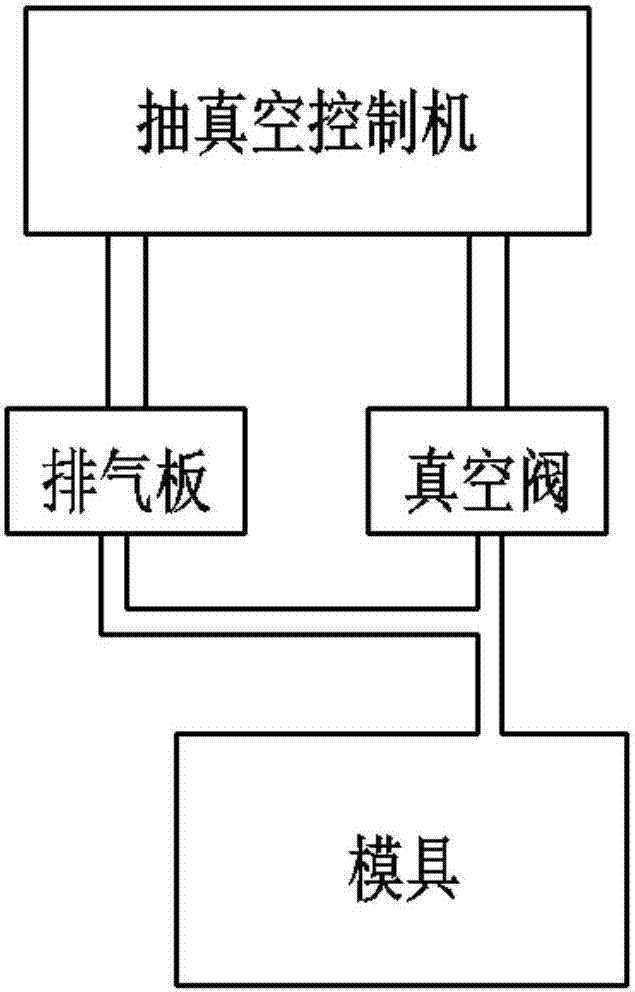
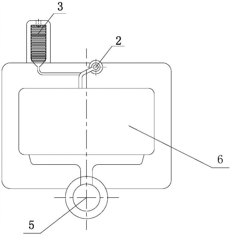
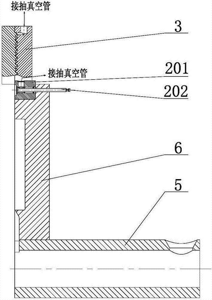
[0032] figure 1 It is a schematic layout diagram of a vacuum pumping structure of a die-casting mold in which a vacuum valve and an exhaust plate are connected in parallel according to an embodiment of the present invention. Such as figure 1 As shown, the vacuum structure includes a vacuum valve 2 , an exhaust block 3 and a vacuum control machine 4 . Wherein, one end of the vacuum valve 2 is ...


PUM


Abstract

The invention discloses a die-casting die vacuumizing structure with a vacuum valve connected with exhaust plates in parallel. The die-casting die vacuumizing structure comprises the vacuum valve (2), an exhaust block (3), a vacuumizing controlling machine (4) and a vacuumizing pipe; one end of the vacuum valve (2) is connected with the vacuumizing controlling machine (4), one end of the exhaust block (3) is connected with the vacuumizing controlling machine (4), and the other end of the vacuum valve (2) and the other end of the exhaust block (3) are connected with a cavity of a die; and the exhaust block (3) comprises the first exhaust plate (301) and the second exhaust plate (305), wherein tooth tops and tooth roots of the first exhaust plate (301) and the second exhaust plate (305) are arranged in a staggered mode, and accordingly, a zigzag and narrow channel is formed. According to the die-casting die vacuumizing structure, the vacuum valve and the exhaust plates are organically combined, and thus, the defect that pores are formed in a die-casting die due to the fact that a vacuumizing valve is closed too early can be well overcome.

Description

technical field [0001] The embodiments of the present invention belong to the technical field of die-casting mold processing, and more specifically, relate to a vacuum-pumping structure of a die-casting mold in which a vacuum valve and an exhaust plate are connected in parallel. Background technique [0002] Die casting is a special casting method with less cutting and no cutting that develops rapidly in modern metal processing technology. It is a process in which molten metal is filled into a mold under high pressure and high speed, and crystallized and solidified under high pressure to form a casting. High pressure and high speed are the main characteristics of die casting. The commonly used pressure is tens of MPa, the filling speed (ingate speed) is about 16-80 m / s, and the time for the molten metal to fill the mold cavity is extremely short, about 0.01- 0.2 seconds. Since casting castings by this method has the advantages of high production efficiency, simple process, ...

Claims


Application Information

Patent Timeline
Patent Type & Authority Applications(China)
IPC IPC(8): B22D17/14B22D17/22
CPCB22D17/14B22D17/22
Inventor 安肇勇
Owner 广东鸿图武汉压铸有限公司
Learn More