
Bridge bottom surface crack detecting method based on binocular vision

A technology of binocular vision and detection method, applied in the direction of optical testing flaws/defects, etc., can solve the problems of high labor cost, low precision, affecting the accuracy of cracks, etc.

Inactive Publication Date: 2017-09-19
CHANGAN UNIV
View PDF2 Cites 30 Cited by
  • Summary
  • Abstract
  • Description
  • Claims
  • Application Information

AI Technical Summary

Problems solved by technology

The cost of renting a large machinery or bridge inspection vehicle is thousands or even tens of thousands of yuan a day, and experts are also needed, which makes the labor cost higher
The second is accuracy. Relying on bridge crack detection experts to search for cracks one by one will obviously lead to the intervention of subjective factors, thus affecting the accuracy of crack finding. Manual measurement of crack size with instruments will inevitably lead to fluctuations in readings. The problem of low precision due to random errors
The fourth is the safety of experts. When experts measure cracks at the bottom of the bridge, some dangers may occur
Although this method is simpler and safer than manual operation, it is difficult for a monocular camera to ensure that the shooting plane of the camera is parallel to the bottom surface of the bridge during the shooting process, so the captured pictures are often the projection of the bottom surface of the bridge on the shooting plane of the camera. The resulting image of the crack is not its true size and cannot reflect its true size
Therefore, the crack size error obtained by this method is large, and the accuracy is relatively low.

Method used


Image

  • Bridge bottom surface crack detecting method based on binocular vision
  • Bridge bottom surface crack detecting method based on binocular vision
  • Bridge bottom surface crack detecting method based on binocular vision

Examples


Embodiment Construction

[0066] The present invention is described in further detail below in conjunction with accompanying drawing:

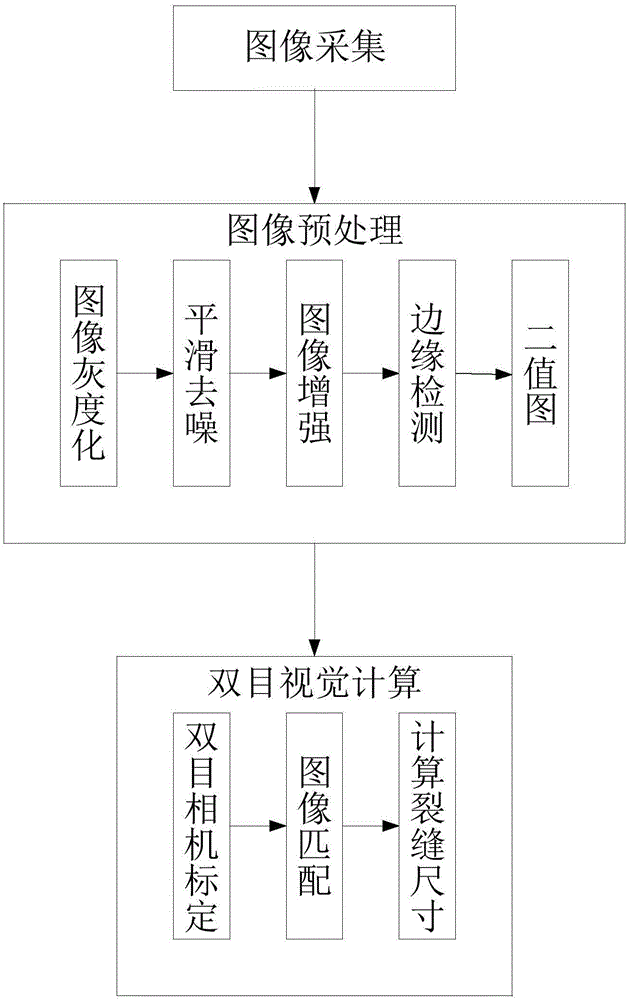
[0067] Such as figure 1 As shown, a binocular vision-based crack detection method on the bottom surface of bridges specifically includes the following steps:

[0068] 4) First, binocular vision dual image acquisition is performed on the bottom of the bridge;

[0069] 5), using the weighted average method to grayscale the double-image crack image obtained in step 1), and then denoising by median filtering, image enhancement is carried out by using the piecewise linear function of the selected threshold, and the Sobel operator is used to perform image enhancement. The crack edge is extracted, and finally the binary image of the crack image is obtained;

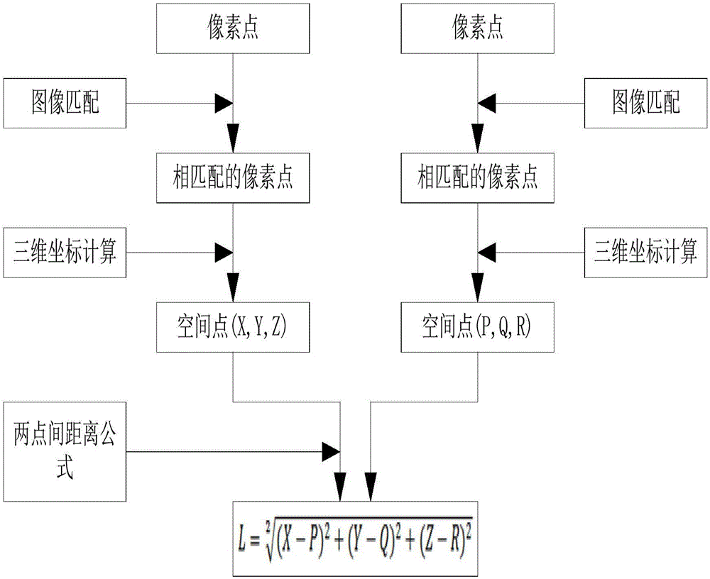
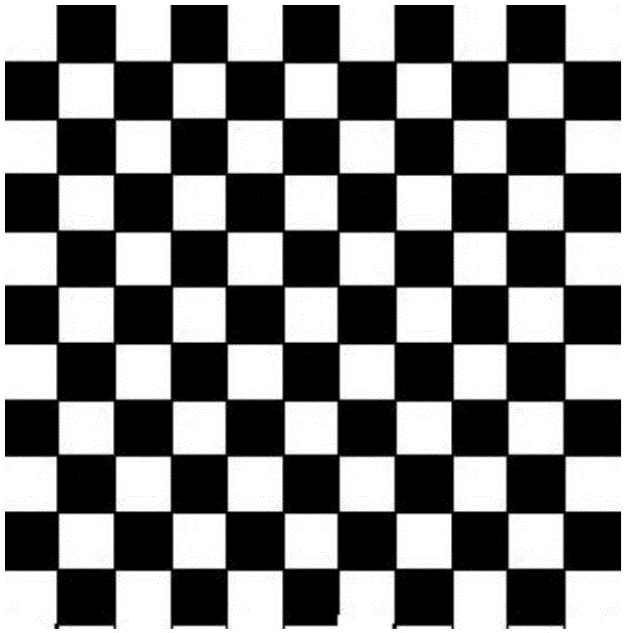
[0070] 6), the dual image collected in step 1) is calibrated by Zhang Zhengyou’s calibration method, and then the binary image obtained in step 2) is matched with the binary image of the obtained crack image using the ...


PUM


Abstract

The invention discloses a bridge bottom surface crack detecting method. The real size of cracks is reduced by binocular vision; the errors are greatly avoided; the condition that in the monocular vision, the shooting plane of a camera in the monocular vision is not parallel to the bridge bottom surface, so that a shot crack image in only the projection of the crack on the shooting plane of a monocular camera is avoided; in the monocular vision, the crack picture is subjected to simple image processing, so that the calculation error is great; only the projection size of the crack on the shooting plane of the monocular camera is obtained; the size is not the real size of the crack; in the image processing aspect, improved median filter is used. Compared with the traditional median filter, the method has the advantages that the condition that all pixel points in the image need to perform median replacement is avoided; only detected noise points need to perform median replacement; by the method, the detail information of the crack in the image is greatly preserved; the excessive smoothing of the crack image after wave filtering is avoided.

Description

technical field [0001] The invention relates to the field of bridge detection, in particular to a method for detecting cracks on the bottom surface of bridges based on binocular vision. Background technique [0002] In recent years, with the rapid development of our country, the bridge engineering in our country has also been greatly developed. The total mileage of bridges in our country has reached an astonishing mileage. Part of it inevitably bears the huge traffic pressure. There are a considerable number of overloaded vehicles in our country, which puts forward a great requirement on the technical condition of bridges. Many bridges have become dangerous bridges before reaching the service life, and the number has been high. The technical condition of bridges is directly Threats to the safety of people's lives have brought the technical condition of the bridge into the spotlight. [0003] Only by increasing the strength and frequency of bridge crack detection can the te...

Claims


Application Information

Patent Timeline
Patent Type & Authority Applications(China)
IPC IPC(8): G01N21/95
CPCG01N21/95
Inventor 韩毅宋定波山岩何爱生高娟
Owner CHANGAN UNIV
Learn More