LNG marine fuel tank system with active upward liquid discharging capacity

A technology for LNG ships and fuel tanks, which is applied to equipment discharged from pressure vessels, pressure vessels, and ship construction details. Effects of operation, reduction of manufacturing and maintenance costs, reduction of manufacturing cost and manufacturing difficulty

Inactive Publication Date: 2017-09-19
CHART CRYOGENIC ENG SYST CHANGZHOU
View PDF0 Cites 2 Cited by
  • Summary
  • Abstract
  • Description
  • Claims
  • Application Information

AI Technical Summary

Problems solved by technology

At present, there are two main liquid discharge methods for LNG marine fuel tanks: one is the bottom liquid discharge method with an external cryogenic submersible pump, and the outer shell of the fuel tank must be made of stainless steel, which has a complex structure and high operating costs; The inner container of the tank adopts a built-in submersible pump, and LNG can be directly pumped out through the submersible pump in the inner container
Compared with the first solution, the daily maintenance of the submersible pump in the tank requires the cryogenic tank (inner shell) to be set up to meet the entrance and exit of the pump body, resulting in a very complicated structure of the cryogenic tank, high cost, and high operating costs
This has brought inconvenience to people's use

Method used


Image

  • LNG marine fuel tank system with active upward liquid discharging capacity
  • LNG marine fuel tank system with active upward liquid discharging capacity

Examples


Embodiment Construction

[0013] The technical solution of this patent will be further described in detail below in conjunction with specific embodiments.

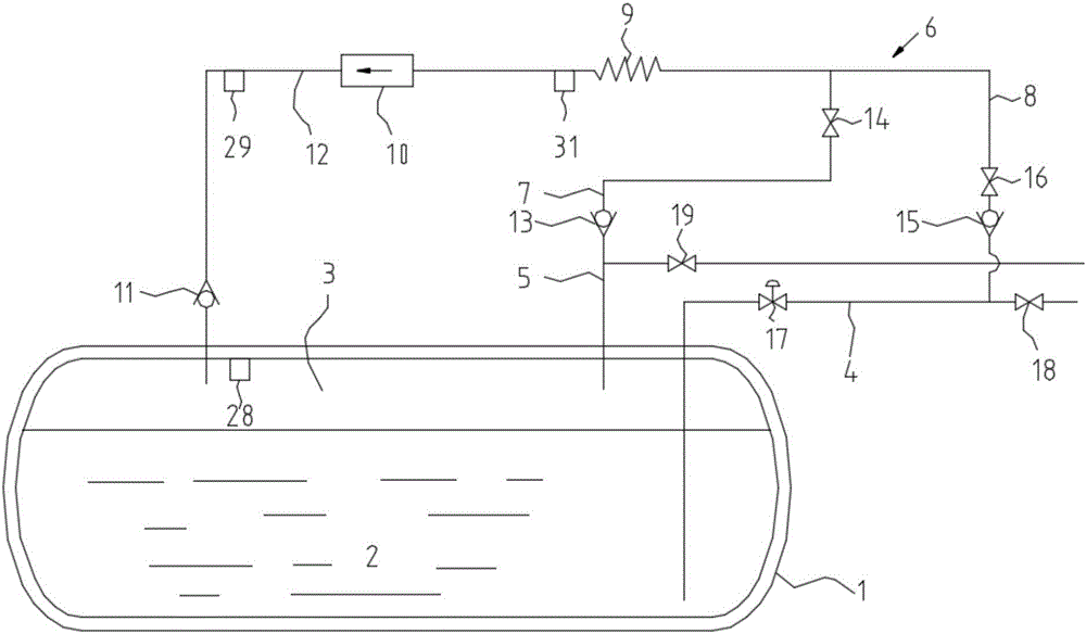
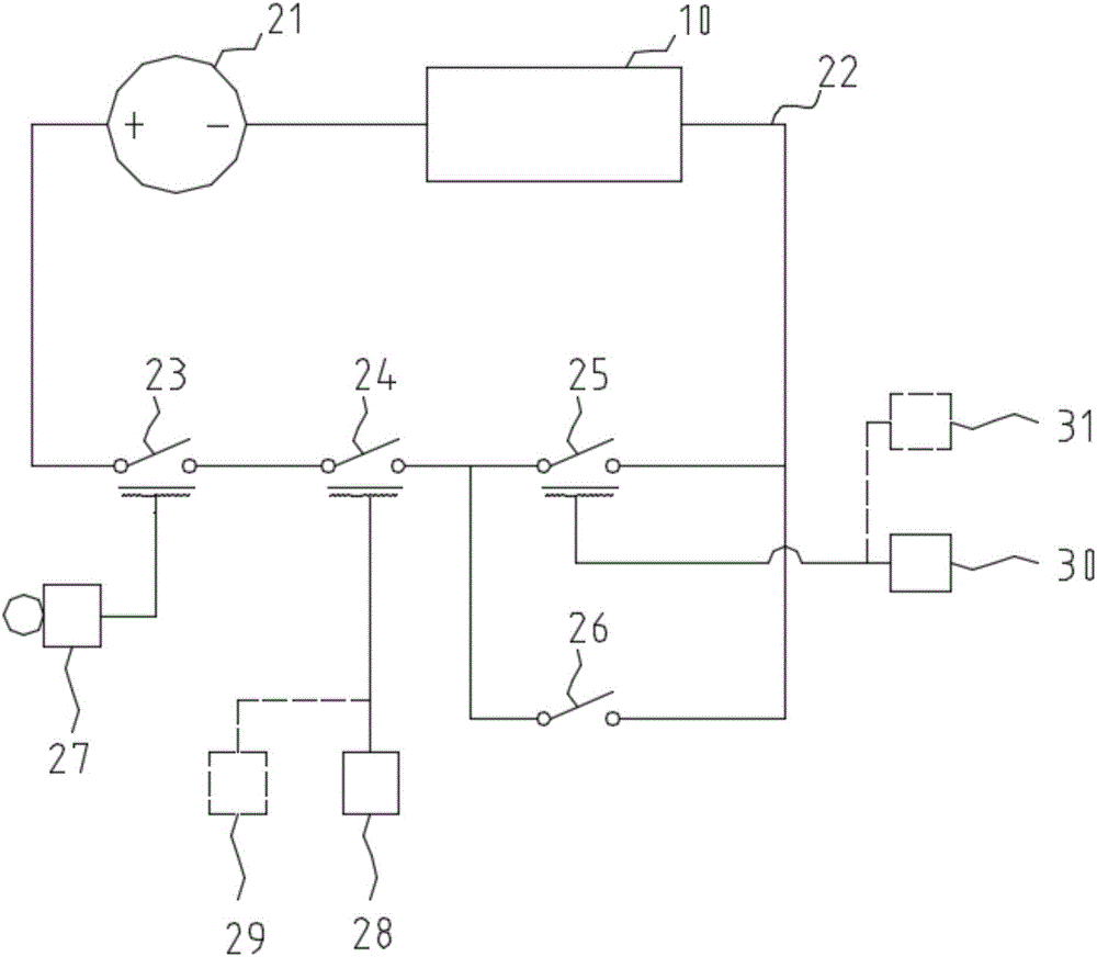
[0014] see Figure 1-2 , a LNG marine fuel tank system with the ability to actively discharge liquid, comprising an electric control box 27, a cryogenic tank body 1, a cryogenic liquid 2, a liquid phase pipeline 4, a gas phase pipeline 5 and a manifold 6, the The cryogenic liquid 2 is located in the inside of the cryogenic tank 1 and the upper end of the cryogenic tank 1 is provided with a first sensor 28, and the upper end of the cryogenic tank 1 is provided with a gas phase space 3, and the first sensor 28 is located in the gas phase space 3 Among them, the liquid phase pipeline 4 communicates with the bottom of the cryogenic tank 1, the liquid phase pipeline 4 is provided with an emergency cut-off valve 17 and a second shut-off valve 18, one end of the gas phase pipeline 5 is connected with the gas phase space 3 and the gas phase The pipeline 5...


PUM


Abstract

The invention discloses an LNG marine fuel tank system with the ability to actively discharge liquid, comprising an electric control box, a cryogenic tank body, a cryogenic liquid, a liquid phase pipeline, a gas phase pipeline and a confluence pipe, the liquid phase pipe The pipeline is connected to the bottom of the cryogenic tank, and one end of the gas phase pipeline is connected to the gas phase space. The confluence pipe is provided with a gas phase inlet and a liquid phase inlet. The gas phase inlet is connected to the gas phase pipeline, and the liquid phase inlet is connected to the liquid phase pipeline. The converging point of the gas phase inlet and the liquid phase inlet is located in the confluence pipe, and a vaporizer, a booster device and a first one-way valve are arranged between the converging point of the gas phase inlet and the liquid phase inlet and the gas phase space to form a circulation loop. This device greatly reduces the manufacturing and maintenance costs of the liquid discharge system on the LNG marine fuel tank. The cryogenic tank is made of carbon steel, which reduces the manufacturing cost of the product, and not only reduces the manufacturing cost and difficulty of the cryogenic pump and related piping systems , which simplifies the daily operation, maintenance work and cost of the liquid discharge system.

Description

technical field [0001] The invention relates to the fuel field, in particular to an LNG marine fuel tank system with the ability to actively discharge liquid. Background technique [0002] The boat uses the buoyancy of water, relying on human power, sails, engines (such as steam engines, gas turbines, diesel engines, nuclear power units), etc., to pull, pull, push, paddle, or push propellers and high-pressure nozzles, so that it can travel on the water. Mobile means of transportation. Modern boats usually have engines with fuel that drive propellers to keep the boat going. At present, there are two main liquid discharge methods for LNG marine fuel tanks: one is the bottom liquid discharge method with an external cryogenic submersible pump, and the outer shell of the fuel tank must be made of stainless steel, which has a complex structure and high operating costs; The inner container of the tank adopts a built-in submersible pump, and LNG can be directly pumped out through ...

Claims


Application Information

Patent Timeline
Patent Type & Authority Applications(China)
IPC IPC(8): F17C7/04F17C13/00F17C13/02F17C13/04
CPCF17C7/04F17C13/00F17C13/025F17C13/04F17C2205/0323F17C2205/0335F17C2221/033F17C2270/0105
Inventor 张炫徐惠新
Owner CHART CRYOGENIC ENG SYST CHANGZHOU
Why Eureka
Try Eureka