Eureka AIR delivers breakthrough ideas for toughest innovation challenges, trusted by R&D personnel around the world.

Novel drill pipe assembling device

A technology for assembling devices and drill pipes, which is applied to drill pipes, drill pipes, drilling equipment, etc., can solve the problems of manual operation required for disassembly, affect work efficiency, and cannot realize automatic work, so as to reduce manual operation and labor costs, improve The effect of work efficiency

Active Publication Date: 2017-09-19
周兆弟
View PDF6 Cites 7 Cited by
  • Summary
  • Abstract
  • Description
  • Claims
  • Application Information

AI Technical Summary

Problems solved by technology

[0003] The existing Chinese patent number is 201510789151.4, and the invention patent named "A Drill Pipe Joint" discloses a drill pipe joint, including a male drill pipe, a female drill pipe, a snap ring and a nut, and the lower end surface of the male drill pipe is set There is an inner stop, the opening of the inner stop is provided with chamfers, the outer wall of the male drill pipe is provided with grooves, and the upper end surface of the female drill pipe is provided with an outer stop that matches the inner stop of the male drill pipe. The outer peripheral wall of the female drill pipe is provided with the same groove as the groove of the male drill pipe, the outer peripheral wall of the snap ring is provided with two external threads, and the inner peripheral wall of the snap ring is provided with up-down symmetrical sealing grooves and bumps. The female drill pipe is positioned and matched through the internal and external spigots, and the snap ring is inserted into the groove on the outer wall of the male drill pipe and the female drill pipe through the protrusion, and the male drill pipe, the female drill pipe and the snap ring are connected into one body, and the outer wall of the snap ring is Two nuts are installed at the two external threads; although the drill pipe joint can withstand forward and reverse rotation in this technology, manual operation is required for its disassembly, and manual operation is required for each section of drill pipe, which greatly affects the work efficiency and cannot realize automatic work

Method used


Image

  • Novel drill pipe assembling device
  • Novel drill pipe assembling device
  • Novel drill pipe assembling device

Examples


Embodiment 1

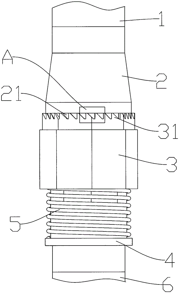
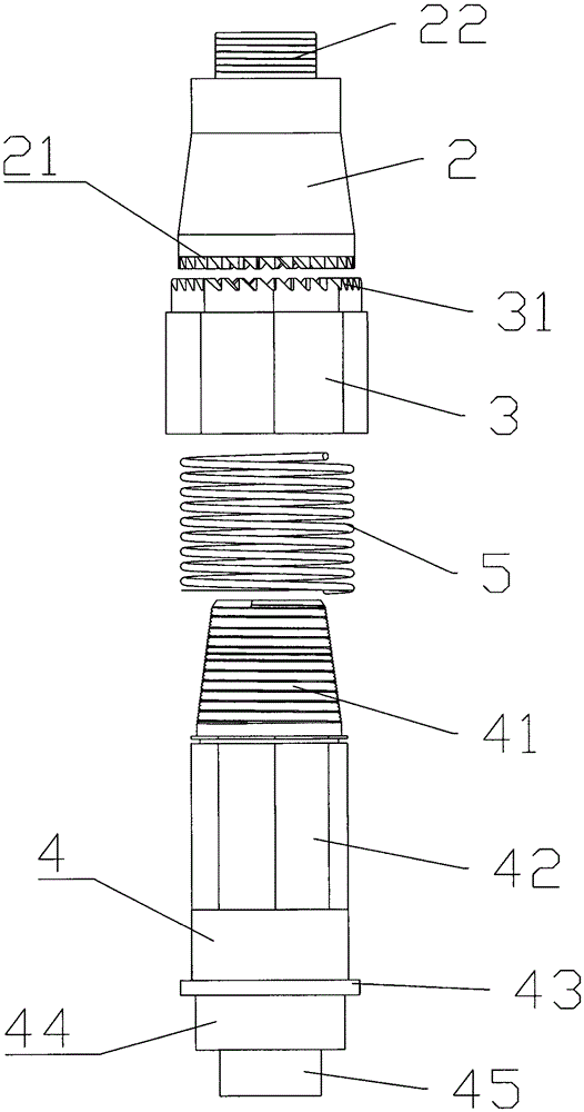
[0026] Such as figure 1 The shown novel drill pipe assembly device of the present invention includes an upper joint 2 and a lower joint 4 connected with an upper drill pipe 1 and a lower drill pipe 6 respectively, and the upper drill pipe 1 is connected with the upper joint 2 and the lower drill pipe 1. The rod 6 and the lower drill bit can be connected in various detachable ways, such as threads, screws, clamping, etc. The upper joint 2 and the lower joint 4 can be rotatably tightened or loosened, and there is a screwable joint between them. threaded connection, and the upper joint 2 and the lower joint 4 are provided with a through channel, the channel is used for pouring mortar, and the lower joint 4 is also fixed with a sliding sleeve 3 in the circumferential direction, and the upper end of the sliding sleeve 3 can be Collision with the lower joint 4 prevents it from rotating in the axial direction. In a specific embodiment, a limit block can be set on the sliding sleeve 3...


PUM


Abstract

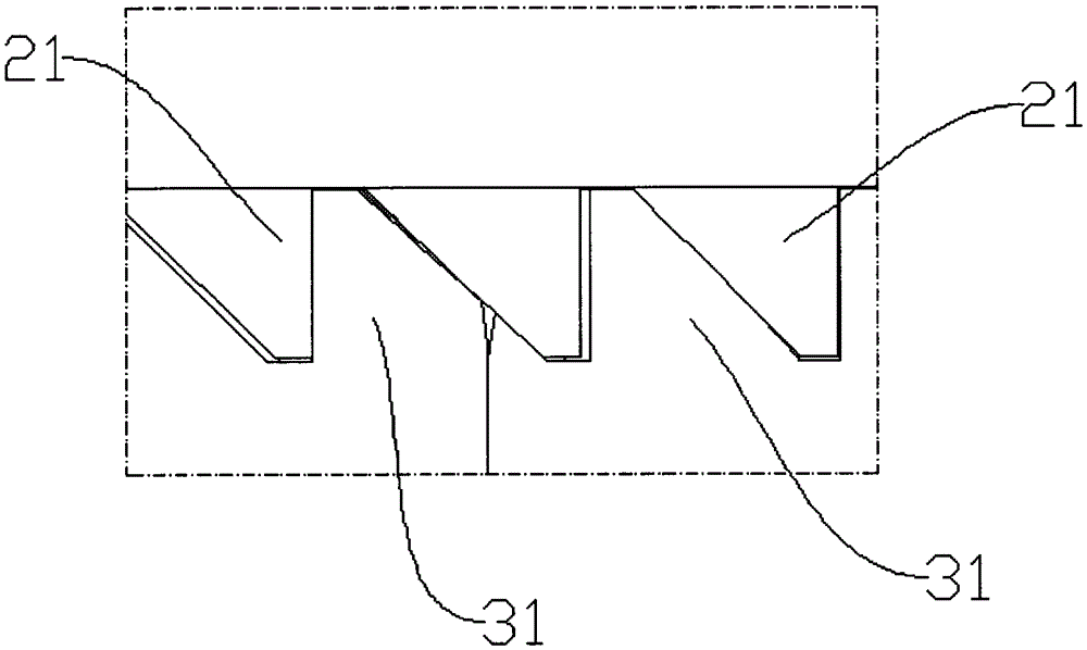
The invention relates to a novel drill pipe assembling device. The novel drill pipe assembling device comprises an upper connector and a lower connector which are connected with an upper drill pipe and a lower drill pipe correspondingly; the upper connector and the lower connector can be rotationally screwed or unscrewed; the upper connector and the lower connector are internally provided with a through channel; a sliding sleeve is circumferentially fixed on the lower connector; the upper end of the sliding sleeve can abut against the lower connector to prevent the lower connector from rotating in the axial direction; and the direction where the sliding sleeve abuts against the upper connector is opposite to the direction where the upper connector and the lower connector are screwed. When the drill pipes rotate forwards, as being in threaded connection, the upper connector and the lower connector can be screwed more and more tightly along with rotation, and when the drill pipes rotate backwards, the sliding sleeve abuts against the upper connector so that the upper connector and the lower connector can be effectively prevented from being unscrewed during backward rotation of the drill pipes. The novel drill pipe assembling device can also achieve automatic mounting and dismounting, manual operation and labor cost are reduced, and the working efficiency is improved.

Description

technical field [0001] The invention relates to a novel drill pipe assembly device, which belongs to the field of construction machinery. Background technique [0002] The large pile driver used on the construction site will be erected at a height of more than 30 to 50 meters, not including the drill pipes that go deep into the ground. As the soil is drilled deeper, the drill pipes are connected one by one. The two drill pipes are connected by a drill pipe joint, and most of the existing drill pipe joints are threaded connections. The threaded connection method is to process one joint into an internal thread and a seam on the end face, and the other joint that is connected with it is processed into an external thread and a seam on the end face, and the drill pipe is driven by the power of the drilling rig to tighten the thread to connect the two sections of the drill pipe. After tightening, the spigot on the end face is in a tight fit state. In the same way, the drill rod ...

Claims


Application Information

Patent Timeline
IPC IPC(8): E21B17/043
CPCE21B17/043
Inventor 周兆弟
Owner 周兆弟
Why Eureka
Eureka Blog
Learn More