
Electrified railway external power grid power supply structure

A technology for electrified railways and external power grids, applied to power lines, vehicle components, transportation and packaging, etc., can solve problems such as power dispatching and switching operation difficulties, and achieve continuity of power supply, good performance, and high power supply reliability Effect

Active Publication Date: 2017-09-19
SOUTHWEST JIAOTONG UNIV
View PDF7 Cites 8 Cited by
  • Summary
  • Abstract
  • Description
  • Claims
  • Application Information

AI Technical Summary

Problems solved by technology

[0006](2) The operation mode without balanced current needs to switch between two substations, making power dispatching and switching operations difficult

Method used


Image

  • Electrified railway external power grid power supply structure
  • Electrified railway external power grid power supply structure
  • Electrified railway external power grid power supply structure

Examples


Embodiment Construction

[0023] Embodiments The present invention will be further described below in conjunction with the drawings and specific embodiments.

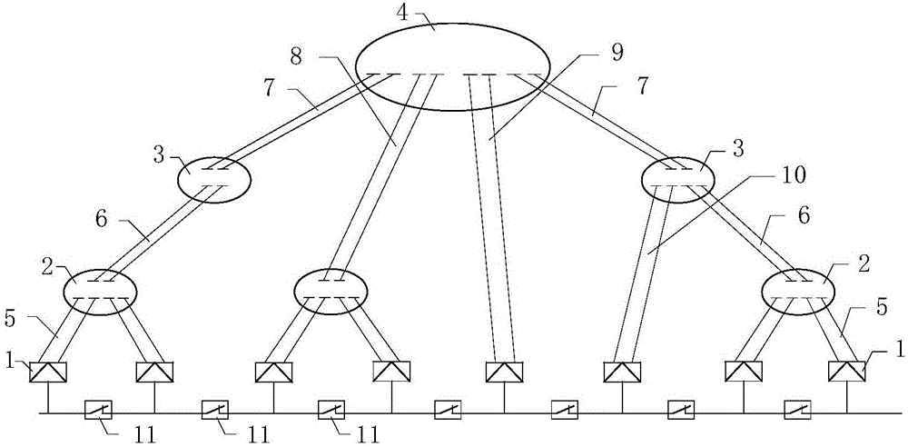
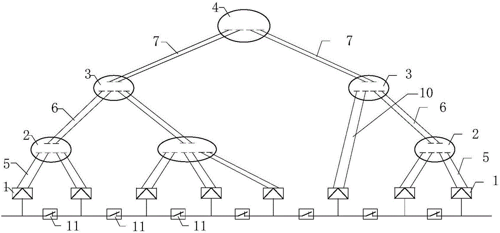
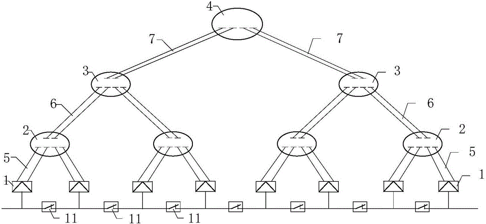
[0024] The external power grid includes substations and transmission lines, which are divided into A-type substations, B-type substations and C-type substations according to the voltage level from high to low; A-type substations feed out 500kV-level voltages, B-type substations feed out 220kV or 330kV-level voltages, and C-type substations feed out 220kV or 330kV-level voltages. Type A substation feeds out 110kV level voltage; Type A substation supplies power to Type B substation, Type C substation and traction substation through transmission line; Type B substation supplies power to Type C substation and traction substation through transmission line; The transmission line supplies power to the traction substation; there are two transmission lines, one for power supply and one for backup, or both work for capacity backup; the traction substation ...


PUM


Abstract

The invention provides an electrified railway external power grid power supply structure. An external power grid comprises transformer substations and power transmission lines; the A-type transformer substation supplies power to the B-type transformer substation, the C-type transformer substation and the traction transformer substations through the corresponding power transmission lines, the B-type transformer substation supplies power to the C-type transformer substation and the traction transformer substations through the corresponding power transmission lines, and the C-type transformer substation supplies power to the traction transformer substations through the corresponding power transmission lines; it is defined that the traction transformer substations serve as leaves, the A-type transformer substation serves as a root, the B-type transformer substation and the C-type transformer substation between the A-type transformer substation and the traction transformer substations serve as nodes; through the power transmission lines, the A-type transformer substation, the B-type transformer substation, the C-type transformer substation and the traction transformer substations are connected into a tree-shaped-structure power supply network from the high-voltage level to the low-voltage level; as long as every two adjacent traction transformer substations (leaves) upwards retrospect and can find the same node or root, the intervening subarea substations can communicate, cut-through power supply is implemented, and an equalizing current cannot be generated; and every two corresponding power transmission lines are arranged into one set, capacity standby application is conducted, and traction power supply is not affected under overhauling or breaking down of bus bars of any power transmission line and transformer substation subsection.

Description

technical field [0001] The invention belongs to the technical field of electrified railway power supply, and in particular relates to a power supply mode and an operation mode for an electrified railway traction substation by an external grid. Background technique [0002] In the current electrified railway, in order to distribute the single-phase traction load as evenly as possible in the three-phase power system, the traction network adopts the scheme of alternating phase sequence and phase-separated and partitioned power supply. Insulation devices or insulating anchor segment joints are used to divide the adjacent power supply areas at the phase separation partition to form electrical phase separation, also known as phase separation. Usually, electric phase splitting is set at the exit of the traction substation and the partition between two adjacent traction substations. Electric split phase is the weakest link of the traction network and the bottleneck of power supply....

Claims


Application Information

Patent Timeline
Patent Type & Authority Applications(China)
IPC IPC(8): B60M3/00
CPCB60M3/00Y02E40/50
Inventor 李群湛郭锴解绍锋赵艺
Owner SOUTHWEST JIAOTONG UNIV
Learn More