Motor drive device
A driving device and motor technology, which is applied in the direction of AC motor deceleration device, power consumption device, motor control, etc., and can solve problems such as voltage rise, battery failure, overvoltage drop, etc.
- Summary
- Abstract
- Description
- Claims
- Application Information
AI Technical Summary
Problems solved by technology
Method used
Image


Examples
Embodiment approach 1
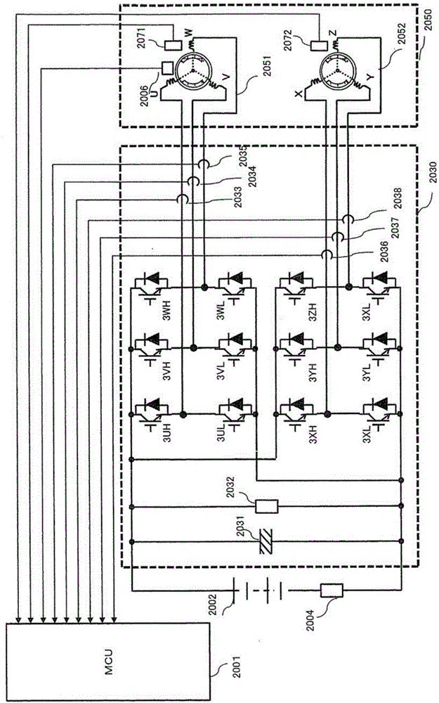
[0046] image 3 It is a flowchart of processing for judging permission / permission of PWM control in the motor drive device according to Embodiment 1 of the present invention. That is to say, MCU2001 passes image 3 The procedure of processing is used to determine whether the dual three-phase inverter 2030 performs PWM control. MCU 2001 has a memory (not shown), and stores a PWM enable / disable flag in the memory. MCU2001 based on image 3 According to the judgment result in the process, the PWM permission / disallow flag stored in the memory is set to allow or not. image 3 The processing of the flowchart is performed in a failure judgment unit (not shown) provided in MCU2001. Next, detailed description will be given.
[0047] First, in step S3001, the MCU 2001 judges whether the dual three-phase inverter 2030 fails. The failure of the dual three-phase inverter 2030 is considered to be, for example, a failure of the current sensor 2004, a failure of the voltage sensor 2032,...
Embodiment approach 2
[0084] Figure 5 It is a flowchart of processing for switching and executing all-phase disconnection, three-phase short-circuit, and PWM based on various conditions in the motor drive device according to Embodiment 2 of the present invention. Figure 5 The processing of the flowchart is executed by a switching unit (not shown) provided in the MCU 2001 . Other configurations and operations are the same as those in Embodiment 1.
[0085] Figure 5 Steps S5001, S5002, S5004, S5101, S5201 in the Figure 4 Steps S4001, S4002, S4004, S4101, and S4201 are the same, so their descriptions are omitted here.
[0086] In the present embodiment, in step S5003 , MCU 2001 determines whether or not the induced voltage of dual three-phase motor 2050 is equal to or less than a preset second threshold value. If the induced voltage is not below the second threshold, proceed to step S5101, perform a process of becoming a three-phase short circuit, and end Figure 5 process of processing. If ...
Embodiment approach 3
[0091] Figure 6 It is a flowchart of a process of switching and executing all-phase disconnection, three-phase short-circuit, and PWM based on various conditions in the motor drive device for a vehicle according to the embodiment of the present invention. Figure 6 The processing of the flowchart is executed by a switching unit (not shown) provided in the MCU 2001 . Other configurations and operations are the same as those in Embodiment 1 or 2 above.
[0092] Figure 6 Steps S6001, S6002, S6004, S6101, S6201 in the Figure 4 Steps S4001, S4002, S4004, S4101, and S4201 are the same, so their descriptions are omitted here.
[0093] In the present embodiment, in step S6003, MCU 2001 obtains the estimated induced voltage of dual three-phase motor 2050, and determines whether the estimated induced voltage is equal to or less than a predetermined third threshold value. If the estimated induced voltage is not less than the third threshold, proceed to step S6101, perform a proces...
PUM
 Abstract
Description
Claims
Application Information
 - R&D
- Intellectual Property
- Life Sciences
- Materials
- Tech Scout
- Unparalleled Data Quality
- Higher Quality Content
- 60% Fewer Hallucinations
Browse by: Latest US Patents, China's latest patents, Technical Efficacy Thesaurus, Application Domain, Technology Topic, Popular Technical Reports.
© 2025 PatSnap. All rights reserved.Legal|Privacy policy|Modern Slavery Act Transparency Statement|Sitemap|About US| Contact US: help@patsnap.com