
Motor damping heat radiation housing structure

A heat dissipation shell and shell technology, which is applied in the direction of the casing/cover/support, electrical components, electromechanical devices, etc., can solve the problems of poor heat dissipation of the motor casing, affecting the use of the motor, impact, etc., so as to improve the comfort of use and prolong Effect of service life and reduction of vibration amplitude

Pending Publication Date: 2017-09-15
楼奇杰
View PDF0 Cites 10 Cited by
  • Summary
  • Abstract
  • Description
  • Claims
  • Application Information

AI Technical Summary

Problems solved by technology

[0002] A motor refers to an electromagnetic device that converts or transmits electrical energy according to the law of electromagnetic induction, or converts one form of electrical energy into another form of electrical energy. The motor converts electrical energy into mechanical energy (commonly known as a motor), and the generator is It converts mechanical energy into electrical energy. Its main function is to generate driving torque as a power source for electrical appliances or various machines. The motor will generate a lot of heat energy when it works for a long time, especially when the weather is hot. The heat dissipation of the motor shell is poor, and it may even be burnt out, which cannot be discovered by people, and the traditional motor has poor shock resistance, and it will collide with the ground, causing a lot of noise and affecting the use of the motor. Therefore, it is necessary to solve the above problems of the motor make improvements

Method used


Image

  • Motor damping heat radiation housing structure
  • Motor damping heat radiation housing structure

Examples


Embodiment Construction

[0017] The following will clearly and completely describe the technical solutions in the embodiments of the present invention with reference to the accompanying drawings in the embodiments of the present invention. Obviously, the described embodiments are only some, not all, embodiments of the present invention. Based on the embodiments of the present invention, all other embodiments obtained by persons of ordinary skill in the art without making creative efforts belong to the protection scope of the present invention.

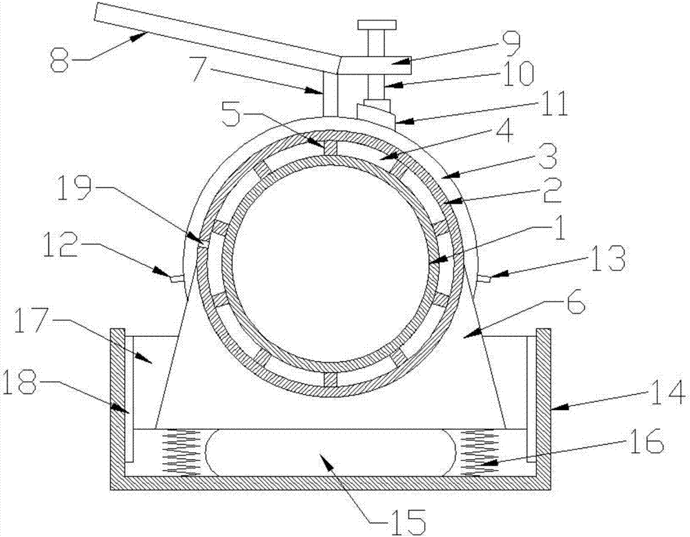
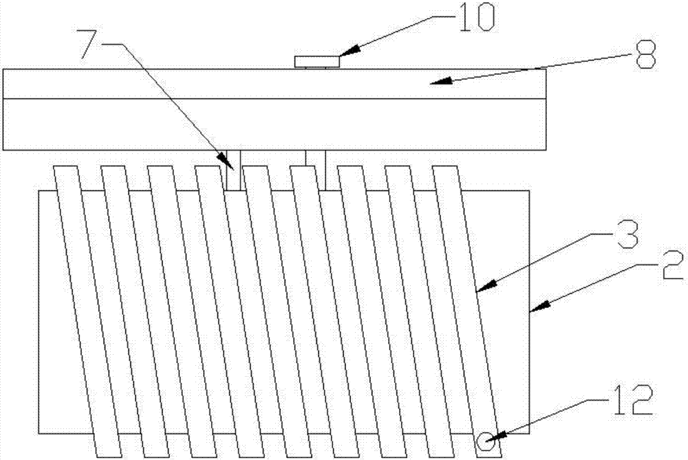
[0018] Please refer to the figure, in an embodiment of the present invention, a motor shock-absorbing and heat-dissipating shell structure includes a casing 1, a water jacket 2, a mounting seat 6 and a casing 14; A water cavity 4 is arranged between the cover 2 and the casing 1, and the thickness of the water cavity 4 is 10-20mm. Several support blocks 5 are arranged in the water cavity 4, and the support blocks 5 support the water jacket 2; The outer side is ...


PUM

PropertyMeasurementUnit
Thicknessaaaaaaaaaa
Angleaaaaaaaaaa

Abstract

The invention discloses a motor damping heat radiation housing structure. The motor damping heat radiation housing structure comprises a motor housing, a water jacket, an installation seat and a casing; a water jacket is arranged on the outer side of the motor housing; a water chamber is formed between the water jacket and the motor housing; a spiral-structured heat absorption pipe is arranged on the outside of the water jacket; a damping air bag and a damping spring are arranged between a casing bottom and an installation seat bottom; friction blocks are fixedly arranged on two sides of the installation seat; friction mats are arranged on the housing which correspond to the friction blocks; an inclined wind guiding plate is fixedly connected to the upper end of the rotation shaft; and a vertical fixing bolt is installed on a regulation plate through a screw thread. The motor damping heat radiation housing structure can guide surrounding air to blow to a mechanism through arrangement of a wind-guiding plate, so that the heat of heat radiation members can be quickly transmitted to the air flowing through and efficiently takes the heat away, greatly reduces temperature of the motor, enables the motor to operate smoothly and extends the service life of the motor.

Description

technical field [0001] The invention relates to the field of motors, in particular to a motor shock-absorbing and heat-dissipating shell structure. Background technique [0002] A motor refers to an electromagnetic device that converts or transmits electrical energy according to the law of electromagnetic induction, or converts one form of electrical energy into another form of electrical energy. The motor converts electrical energy into mechanical energy (commonly known as a motor), and the generator is It converts mechanical energy into electrical energy. Its main function is to generate driving torque as a power source for electrical appliances or various machines. The motor will generate a lot of heat energy when it works for a long time, especially when the weather is hot. The heat dissipation of the motor shell is poor, and it may even be burnt out, which cannot be discovered by people, and the traditional motor has poor shock resistance, and it will collide with the g...

Claims


Application Information

Patent Timeline
IPC IPC(8): H02K5/20H02K5/24H02K9/04
CPCH02K5/20H02K5/24H02K9/04
Inventor 楼奇杰季燎原
Owner 楼奇杰
Learn More