
Pixel circuit and display panel

A technology of pixel circuits and power signals, applied in static indicators, instruments, etc., can solve the problems of driving transistor threshold voltage drift, poor response speed, and poor response speed.

Inactive Publication Date: 2017-09-15
BOE TECH GRP CO LTD +1
View PDF6 Cites 10 Cited by
  • Summary
  • Abstract
  • Description
  • Claims
  • Application Information

AI Technical Summary

Problems solved by technology

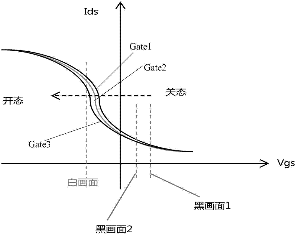
[0003] However, by testing the OLED display screen, it is found that the response speed of the OLED display screen is poor when jumping from the dark state display screen to the bright state display screen
This is because the off-state voltage of the drive transistor that drives the OLED to emit light in the off-state is relatively large (in order to ensure the contrast of the display screen, the off-state voltage needs to be set relatively high so that the drive transistor is in a completely cut-off state), so when the display When the screen jumps from the dark state to the bright state, the driving transistor will experience a short-term threshold voltage drift, resulting in poor response speed and hysteresis effect

Method used


Image

  • Pixel circuit and display panel
  • Pixel circuit and display panel
  • Pixel circuit and display panel

Examples


Embodiment Construction

[0046] The specific implementation manners of the pixel circuit and the display panel provided by the embodiments of the present invention will be described in detail below with reference to the accompanying drawings.

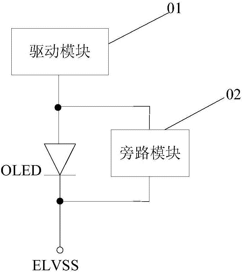
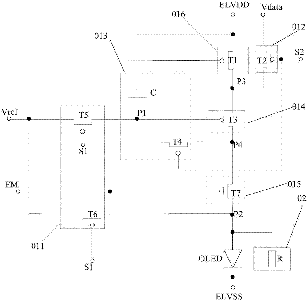
[0047] An embodiment of the present invention provides a pixel circuit, such as figure 1 As shown, it includes: a driving module 01, a bypass module 02 and a light-emitting device OLED; wherein, the driving module 01 is used to input a driving current to the input terminal of the light-emitting device OLED to drive the light-emitting device OLED to emit light; the bypass module 02 is connected to the light-emitting device Between the input terminal and the output terminal of the OLED is used to divide the driving current input by the driving module 01 to the light emitting device OLED, and the output terminal of the light emitting device is connected to the ground power signal ELVSS.

[0048] Specifically, a response time test is performed on the display panel. D...


PUM


Abstract

The invention discloses a pixel circuit and a display panel. The pixel circuit comprises a driving module, a bypass module and a light emitting device. The driving module is used to input driving current to the input end of the light emitting device to drive the light emitting device to emit light. The bypass module is connected between the input end and the output end of the light emitting device, and is used to shunt the driving current input by the driving module to the light emitting device. The off-state voltage of the driving module can be set to be smaller, so that the driving module in a dark state can output trace current to protect response time, improve response speed and improve a hysteresis effect. The bypass module is connected between the input end and the output end of the light emitting device, and then the current through the light emitting device is small through the shunt of the bypass module. The brightness of the light emitting device in a dark state is dark enough to ensure that the dark state display brightness of the display panel.

Description

technical field [0001] The present invention relates to the field of display technology, in particular to a pixel circuit and a display panel. Background technique [0002] With the advancement of display technology, Organic Light Emitting Diode (OLED) is one of the hotspots in the field of flat panel display research today, and more and more Active Matrix Organic Light Emitting Diode (AMOLED) display Panels have entered the market. Compared with traditional thin film transistor liquid crystal display panels (Thin Film Transistor Liquid Crystal Display, TFT LCD), AMOLED has faster response speed, higher contrast ratio and wider viewing angle. [0003] However, it is found through testing the OLED display screen that the response speed of the OLED display screen is poor when jumping from a dark state display picture to a bright state display picture. This is because the off-state voltage of the drive transistor that drives the OLED to emit light in the off-state is relativel...

Claims


Application Information

Patent Timeline
Patent Type & Authority Applications(China)
IPC IPC(8): G09G3/3233
CPCG09G3/3233
Inventor 孙阔皇甫鲁江尹海军刘健强王杨
Owner BOE TECH GRP CO LTD
Learn More