Controllable time-lapse faucet

A faucet and pipeline technology, applied in the field of controllable time-delay faucets, can solve the problem of unsustainable water supply from time-delay faucets

Active Publication Date: 2017-09-15
余成鹏
View PDF6 Cites 4 Cited by
  • Summary
  • Abstract
  • Description
  • Claims
  • Application Information

AI Technical Summary

Problems solved by technology

[0006] The purpose of the present invention is to solve the problem that the time-delay faucet cannot supply water continuously, and provide a controllable time-delay faucet, which can delay water supply, and can also provide continuous water supply according to the needs of users

Method used


Image

  • Controllable time-lapse faucet
  • Controllable time-lapse faucet

Examples


Embodiment Construction

[0018] The present invention will be further described below in conjunction with the accompanying drawings.

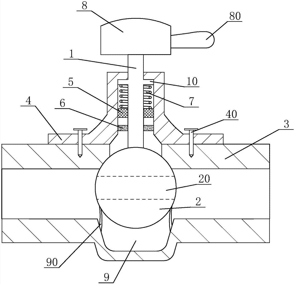
[0019] Such as Figures 1 to 2 A controllable time-delay faucet shown includes a pipe 3 , a valve cover 4 , a valve core 2 , a central rod 1 , a handle, a fixing block 5 and a sealing ring 6 . The bonnet 4 is located above the pipe 3, the fixed block 5 is fixed on the inner wall of the bonnet 4, the central rod 1 passes through the fixed block 5, the fixed block 5 can make the central rod 1 more stable, and the two ends of the central rod 1 are respectively connected to the handle and the valve core 2. The spool 2 is located inside the pipe, and the handle is located above the valve cover 4.

[0020] The valve cover is fixed above the pipeline by fasteners 40 (such as bolts, screws, etc.), which facilitates the disassembly and installation of the valve cover. When the inside of the faucet is damaged, the valve casing can be removed through the fasteners 40, so as to p...


PUM


Abstract

The invention discloses a controllable time-lapse faucet. The controllable time-lapse faucet comprises a pipe, a pressing type handle, a central rod and a valve element which rotates to control opening and closing, wherein the two ends of the central rod are connected with the valve element and the handle, a fixing block and a sealing ring are further arranged between the pipe and the central rod, the central rod penetrates through the fixing block and the sealing ring, and the central rod is connected with the pipe and the fixing block in a sliding manner; the central rod is connected with the valve element and the handle and moves up and down perpendicular to the pipe, a water-proof elastic plate is connected to the portion, on the lower portion of the valve element, of the inner wall of the pipe, and the elastic plate is tightly attached to the valve element; and a baffle ring is arranged on the portion, located on the upper portion of the fixing block, of the outer wall of the central rod, the central rod is sleeved with an elastic part which enables the central rod to reset upwards, and the elastic part is located between the baffle ring and the fixing block. The handle can be pressed downwards and can also be rotated, continuous water supply of the time-lapse faucet can be achieved, and the faucet can be automatically closed after water supply is conducted for a period of time.

Description

[0001] The present invention is a divisional case of the application number 201510789807.2, the application date is November 16, 2015, and the name is controllable delay faucet. technical field [0002] The invention relates to the technical field of hardware valve equipment, which is a controllable delay faucet. Background technique [0003] The faucet is another name for a valve. The structure of the valve includes a valve body, a valve cavity is arranged in the valve body, a valve core is installed in the valve cavity, and a valve stem is connected to the valve core. Various valves are used in various fields such as agriculture and industry. However, there are few valve bodies with multiple methods for controlling liquid flow, which cannot meet the needs. [0004] At present, time-delay faucets on the market are mostly found in public drinking fountains, public toilets, etc. There are many types of time-delay faucets, including mechanical ones and infrared ones. The time...

Claims


Application Information

Patent Timeline
Patent Type & Authority Applications(China)
IPC IPC(8): F16K21/08F16K5/06F16K5/20
CPCF16K5/0605F16K5/0647F16K5/0689F16K5/201F16K21/08
Inventor 余成鹏
Owner 余成鹏
Why Eureka
Try Eureka