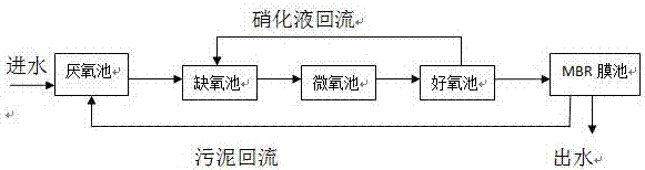
Anaerobic-anoxic-aerobic-microaerobic-membrane component treatment device
A technology of treatment device and membrane module, which is applied in aerobic and anaerobic process treatment, water treatment parameter control, biological water/sewage treatment, etc. question
- Summary
- Abstract
- Description
- Claims
- Application Information
AI Technical Summary
Problems solved by technology
Method used
Image

Examples
Embodiment 1
[0020] Implement this patent at the sewage treatment construction site.
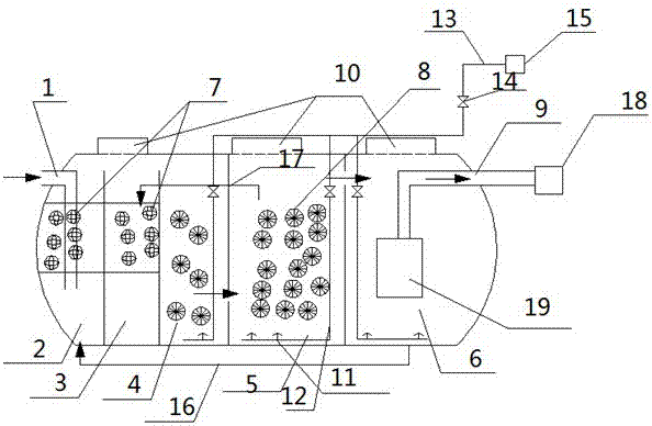
[0021] A2O2+MBR treatment device includes: water inlet 1, anaerobic pool 2, anoxic pool 3, micro-aerobic pool 4, aerobic pool 5, membrane pool 6, spherical packing 7, MBBR packing 8, MBR membrane module 19, outlet pipe 9. Inspection port 10, aeration device, sludge return pipe 16, nitrification liquid return pipe 17, self-priming pump 18; aeration device refers to aeration head 11, aeration branch pipe 12, aeration main pipe 12, gas regulating valve 14. Aeration equipment 15; a biological filter bed is installed in the anaerobic tank 2 and the anoxic tank 3, and a spherical filler 7 is placed in the biological filter bed, and the spherical filler 7 in the biological filter bed is fixed; MBBR filler 8 is placed in pool 4 and aerobic pool 5, and MBBR filler 8 is removable; MBR membrane module 19 is installed in membrane pool 6; The tops of the aerobic pool 5 and the membrane pool 6 are equipped with an in...
Embodiment 2
[0029]The upper filter plate of the biological filter bed is 98mm from the lower end of the outlet pipe, and the lower filter plate of the biological filter bed is 385mm from the bottom.
[0030] The rest are the same as above and will not be repeated.
Embodiment 3
[0032] The upper filter plate of the biological filter bed is 168mm from the lower end of the outlet pipe, and the lower filter plate of the biological filter bed is 428mm from the bottom.
[0033] The rest are the same as above and will not be repeated.
PUM
 Abstract
Description
Claims
Application Information
 - R&D
- Intellectual Property
- Life Sciences
- Materials
- Tech Scout
- Unparalleled Data Quality
- Higher Quality Content
- 60% Fewer Hallucinations
Browse by: Latest US Patents, China's latest patents, Technical Efficacy Thesaurus, Application Domain, Technology Topic, Popular Technical Reports.
© 2025 PatSnap. All rights reserved.Legal|Privacy policy|Modern Slavery Act Transparency Statement|Sitemap|About US| Contact US: help@patsnap.com