Prism structure of optical machine

A prism and light-mechanical technology, applied in the field of projectors, can solve the problems of cumbersome, prism imaging, easy out of focus, debugging and assembly process, etc.

Active Publication Date: 2017-09-08
SHENZHEN EVIEWTEK TECH CO LTD
View PDF8 Cites 5 Cited by
  • Summary
  • Abstract
  • Description
  • Claims
  • Application Information

AI Technical Summary

Problems solved by technology

[0005] The purpose of the present invention is to provide an optical-mechanical triangular prism structure to avoid the problems that the triangular prism imaging is easy to run out of focus and the debugging and assembly process is cumbersome

Method used


Image

  • Prism structure of optical machine
  • Prism structure of optical machine
  • Prism structure of optical machine

Examples


Embodiment Construction

[0026] The core of the present invention is to provide an optical-mechanical triangular prism structure, so as to avoid the problems that the triangular prism image is easily out of focus and the debugging and assembly process is cumbersome.

[0027] In order to enable those skilled in the art to better understand the technical solutions provided by the present invention, the present invention will be further described in detail below in conjunction with the accompanying drawings and specific embodiments.

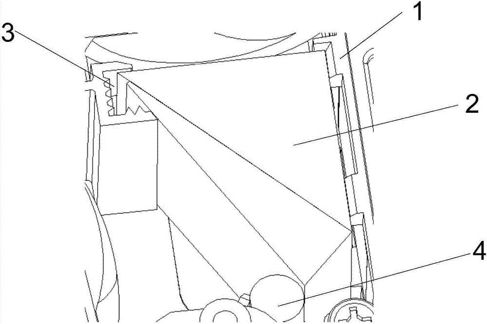
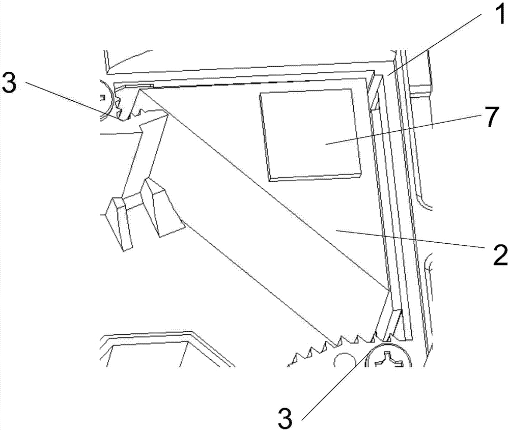
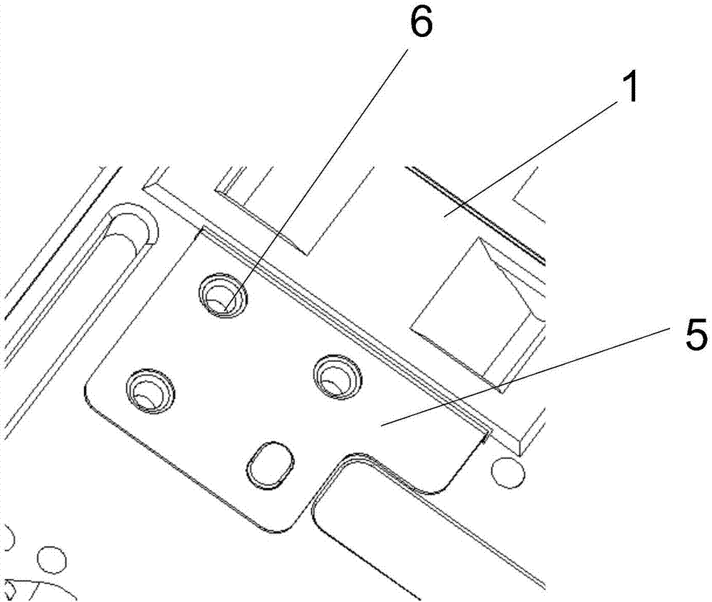
[0028] Such as Figure 4-Figure 7 As shown, the prism structure of an optical machine provided by the embodiment of the present invention includes an optical machine body 1 and a prism 2 fixed on the optical machine body 1. The optical machine body 1 is provided with a first bearing surface 8, a second Abutment surface 9 and limit surface 10; the first abutment surface 8 fits with the first side of the prism 2, the second abutment surface 9 fits with the second side of the ...


PUM


Abstract

The invention discloses a prism structure of an optical machine. The prism structure comprises an optical machine body and a prism fixed to the optical machine body, the optical machine body is provided with a first bearing surface, a second bearing surface and a limiting surface, the first bearing surface is attached to a first side surface of the prism, the second bearing surface is attached to a second side surface of the prism, and a supporting and tightening device is arranged between the limiting surface and a third surface of the prism. According to the prism structure of the optical machine, the first side surface of the prism is limited through the first bearing surface, the second side surface of the prism is limited through the second bearing surface, the third side surface of the prism and the limiting surface are supported and tightened through the supporting and tightening device to realize fixing, the position precision of the prism is guaranteed mainly through the machining precision of the first bearing surface and the second bearing surface, and the problems that in dispensing and debugging processes, focus deviation during imaging of the prism easily occurs and the debugging and assembling processes are complicated are avoided.

Description

technical field [0001] The invention relates to the technical field of projectors, in particular to a triangular prism structure of an optical machine. Background technique [0002] With the development of modern micro-projection technology, more and more optical engines are pursuing requirements such as small size, high brightness, and good imaging quality. One of them is that the assembly and fixing of the optical prism plays a very important role in the imaging quality of the entire product. effect. Usually the prism is fixed by adjusting the jig for calibration, and then fixing it with UV glue, or adding a rubber rod to realize the fixing operation. [0003] Such as Figure 1-Figure 3 As shown, the existing optical engine engine triangular prism generally includes an optical engine body 1 and a triangular prism 2, and the fixed position of the optical engine body 1 corresponding to the triangular prism 2 is provided with an assembly slot 3, and the triangular prism 2 an...

Claims


Application Information

Patent Timeline
Patent Type & Authority Applications(China)
IPC IPC(8): G02B7/18G03B21/14
CPCG02B7/1805G03B21/14Y02P40/57
Inventor 曾艳山王海鹏陆巍贺银波
Owner SHENZHEN EVIEWTEK TECH CO LTD
Why Eureka
Try Eureka