Double magnetic circuit composite optic current transformer and its signal processing method

A current transformer and signal processing technology, applied in the field of dual magnetic circuit composite optical current transformer and its signal processing, can solve the problems of accuracy influence and measurement accuracy decline, and achieve the improvement of steady-state accuracy and transient accuracy, anti-magnetic Good effect of interference ability

Pending Publication Date: 2017-09-08
NORTH CHINA ELECTRIC POWER UNIV (BAODING)
View PDF14 Cites 3 Cited by
  • Summary
  • Abstract
  • Description
  • Claims
  • Application Information

AI Technical Summary

Problems solved by technology

This invention uses composite sensing technology to solve the problem of measurement accuracy of optical current transformers caused by time-varying parameters and improve the measurement accuracy; however, this invention still has shortcomings, which are specifically manifested in: the basic optical path and the vertical polarization optical path , once the vertical self-focusing lens is not perpendicular to the main axis, or there is a difference in performance between the vertical self-focusing lens and the parallel self-focusing lens, the accuracy of the output result will be affected. In addition, due to the direct optical path type optical glass current mutual inductance The openness of the magneto-optical material of the device causes it to be subjected to external electromagnetic interference, which leads to a decrease in measurement accuracy

Method used


Image

  • Double magnetic circuit composite optic current transformer and its signal processing method
  • Double magnetic circuit composite optic current transformer and its signal processing method
  • Double magnetic circuit composite optic current transformer and its signal processing method

Examples


Embodiment Construction

[0044] The embodiments will be described in detail below in conjunction with the accompanying drawings.

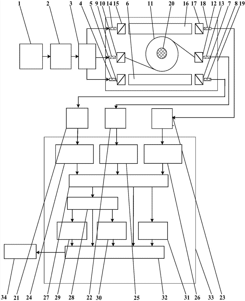
[0045] figure 1 Shown is a schematic diagram of the real-time signal processing scheme of the dual magnetic circuit composite optical current transformer. A dual magnetic circuit composite optical current transformer, including a laser diode driver, a laser diode with pigtails, an optical splitter, a dual magnetic circuit composite magneto-optical sensing unit, and a photodetector; the laser diode driver (1) uses a constant current Or work in constant power mode, used to drive the laser diode (2), the laser diode (2) outputs high and stable DC light intensity, after passing through the optical splitter (3), according to the proportional coefficient K 1 and K 2 Be divided into three beams of light, the first beam of light according to the K of the light intensity of the output light of the laser diode (2) 1 times, through the first input collimator (4), the first polariz...


PUM


Abstract

The invention belongs to the current measurement technology field and more particularly, to a double magnetic circuit composite optic current transformer and its signal processing method, comprising the following elements connected in succession: a laser diode driver, a tail fiber equipped laser diode, a light splitter, a double magnetic circuit composite magnetic light sensing unit and photoelectric detectors wherein the double magnetic circuit composite magnetic light sensing unit comprises three parallel light path channels with each light path channel comprising the following elements connected in succession: an input collimator, a polarizer, magnetic light sensing materials, a polarization detector, and an output collimator, wherein the first magnetic light sensing material and the third magnetic light sensing material are both bar-shaped magnetic light sensing glass and are arranged in parallel and in symmetry at two sides of a powered conductor. The light penetration direction is vertical to the tested current flowing direction of the powered conductor; and the second magnetic light sensing material is a magnetic light sensing fiber that is wrapped on the powered conductor uniformly. The ends of the three light path channels are connected with three different photoelectric detectors respectively. The invention solves the problems with temperature sensitivity and electromagnetic interference.

Description

technical field [0001] The invention belongs to the technical field of current measurement, and in particular relates to a double magnetic circuit composite optical current transformer and a signal processing method thereof. Background technique [0002] In recent years, the operating voltage level of the power grid has been continuously improved, and the continuous operation of high-voltage and high-current power system equipment has put forward higher requirements for the insulation requirements of the primary and secondary sides and the reliable transmission of signals. The traditional electromagnetic Type current transformers have exposed a series of serious problems, such as insulation difficulties, large volume, heavy weight, difficult manufacturing, flammable and explosive, magnetic saturation and resonance, etc. As a new type of electronic current transformer, the optical current transformer uses magneto-optical materials as the sensing medium, and utilizes the uniqu...

Claims


Application Information

Patent Timeline
IPC IPC(8): G01R15/24
CPCG01R15/245
Inventor 李岩松刘君
Owner NORTH CHINA ELECTRIC POWER UNIV (BAODING)
Why Eureka
Try Eureka