
Petroleum wellhead annular space sealing device

A sealing device and annulus technology, which is applied in sealing/isolation, wellbore/well parts, earthwork drilling and production, etc., can solve the problems of high temperature resistance and strength decline of seals, easy failure, and poor high temperature resistance of rubber, etc. , to achieve the effects of small deformation uncertainty, good corrosion resistance and reliable sealing

Pending Publication Date: 2017-09-08
DEZHOU UNITED GASOLINEEUM MACHINERY
View PDF17 Cites 94 Cited by
  • Summary
  • Abstract
  • Description
  • Claims
  • Application Information

AI Technical Summary

Problems solved by technology

[0005] 1. The high temperature resistance of rubber is poor. Although nominally high-grade rubber can withstand high temperatures above 121 degrees Celsius, if it withstands a pressure of 0 to 138 MPa at this high temperature and is a corrosive fluid pressure under a large gap condition, it will be sealed. high failure rate
Imported or domestically replaced imported manufacturers have a high scrap rate and high cost due to their complex processing technology. For example, the market price of a 5-1 / 2″ seal ring is nearly 1,000 yuan.
[0006] 2. The metal skeleton of the seal further increases the processing difficulty of the rubber seal. In addition, based on the positioning of the metal skeleton, most domestically adopt the secondary vulcanization process. Although the problem of fixing the metal skeleton is solved, it also improves the high temperature resistance of the seal. and a substantial decrease in strength
[0011] The above existing technologies generally use rubber parts with relatively large deformation. As mentioned above, rubber parts have relatively low tolerance to ambient temperature and are prone to failure

Method used


Image

  • Petroleum wellhead annular space sealing device
  • Petroleum wellhead annular space sealing device
  • Petroleum wellhead annular space sealing device

Examples


Embodiment Construction

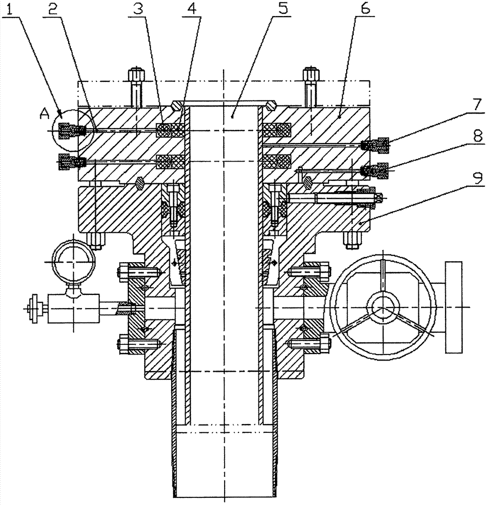
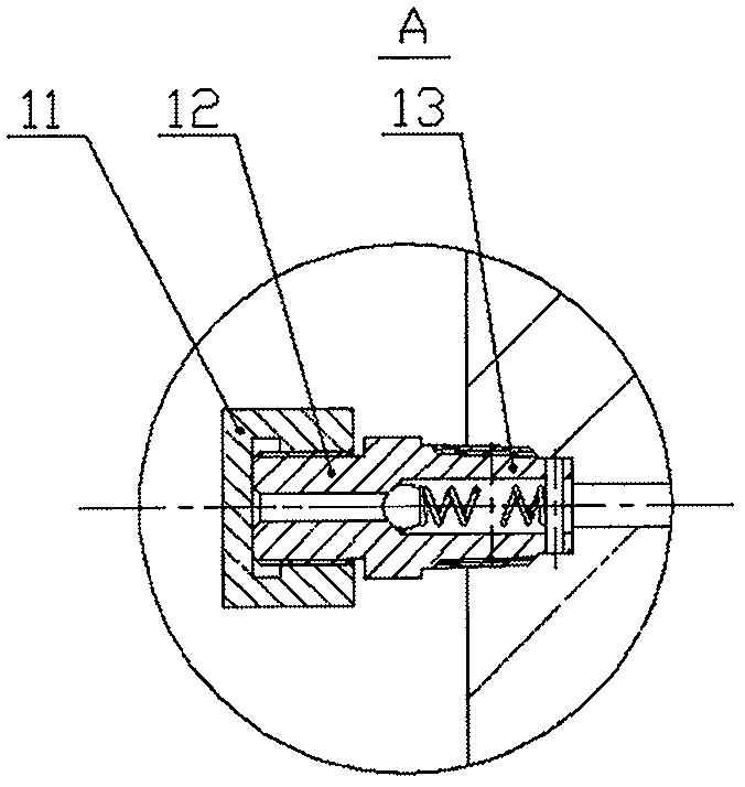
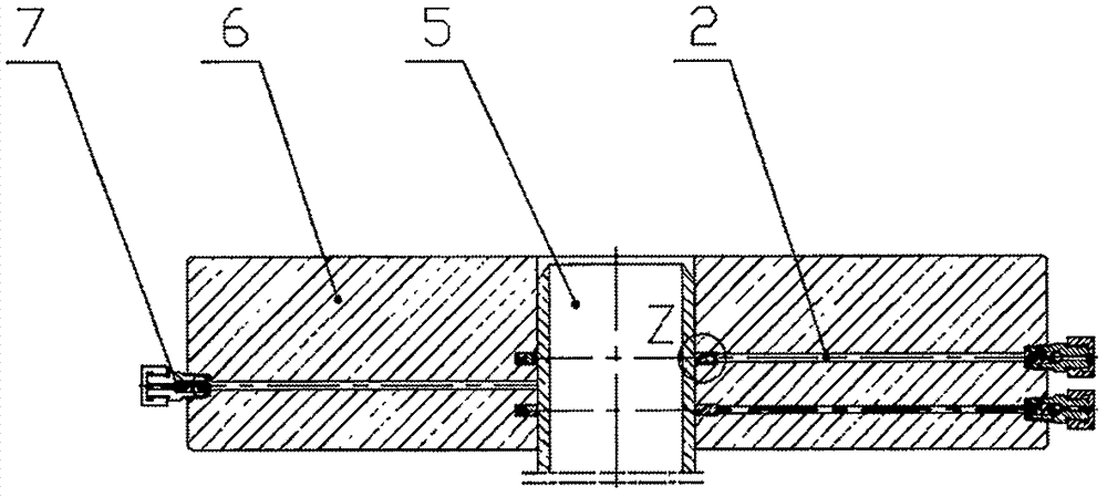
[0037] Refer to the attached figure 1 , is a set of oil wellhead casing heads, and is the assembly structure of the wellhead annulus sealing device on the wellhead equipment in some embodiments. The casing head and the device for sealing the casing annulus, the casing head is the sealing body 6 shown in the figure, which is a part of the oil wellhead (the oil wellhead includes three parts: the casing head, the tubing head and the Christmas tree) .

[0038] As mentioned in the background technology section, there is a relatively large annular space between the sealing body 6 and the oil pipe 5 because the tolerance zone of the oil pipe 5 is relatively wide.

[0039] It will be appreciated that the radial, axial and circumferential directions are generally referenced to the surrounding pipe, based on the pipe and other components fitted around the pipe.

[0040] then if image 3 The oil wellhead annular sealing device shown is used to seal the annular space between the wellhe...


PUM


Abstract

The invention discloses a petroleum wellhead annular space sealing device. The petroleum wellhead annular sealing device is used for sealing an annular space between a wellhead sealing body and a petroleum pipe, at least one annular groove is formed in the inner wall surface of the sealing body, and the sealing body is provided with an injection hole which is communicated to a centrifugal end of the annular groove; the petroleum wellhead annular space sealing device further comprises a sealing ring, a power ring, and an injection component, wherein the sealing ring is embedded into the annular groove, the sealing ring is used for sealing the groove in the radial direction by being jointed to the wall surface of the annular groove, and is used for sealing the annular space by being jointed to the outer wall of the petroleum pipe, the power ring is installed in the annular groove and is located between the groove bottom of the annular groove and the sealing ring, and the injection component is installed in an inlet of the injection hole, and is used for injecting fluid with given pressure so as to make the power ring push the sealing ring to tightly press the petroleum pipe. In the petroleum wellhead annular space sealing device, the requirement for deformation capability of a sealing part is low, and meanwhile the sealing capability can be effectively improved.

Description

technical field [0001] The invention relates to an oil well head annular space sealing device. Background technique [0002] The most commonly used operating temperature range for oil drilling and oil production is KU (-60°C to 121°C), the operating temperature range is relatively large, and the outer circle tolerance of oil pipes is calculated as 5.5 inches of oil pipes, and the outer circle tolerance is its diameter +1 %D to -0.5%D (the reason why the oil pipe sealing gap is much larger than that in the hydraulic industry is that the sealing surface of the oil pipe, that is, the outer diameter of the oil pipe has a large tolerance), where D is the outer diameter of 5.5 inches. An annulus will be formed between the resulting oil pipe and the sealing body (i.e. the wellhead device) sleeved on the oil pipe, and the sealing of the annulus part should have a sealing capacity of at least 2.495 mm gap. Such a large gap is a test for any rubber seal, and the working conditions ar...

Claims


Application Information

Patent Timeline
IPC IPC(8): E21B33/03
CPCE21B33/03
Inventor 李海庆唐建平薛庆华程贵华侯祖刚
Owner DEZHOU UNITED GASOLINEEUM MACHINERY
Learn More