
Heat pump system

A heat pump system and heat exchanger technology, applied in lighting and heating equipment, mechanical equipment, fluid circulation arrangements, etc., can solve the problems of not being able to adapt to the needs of different working conditions

Pending Publication Date: 2017-09-01
GREE ELECTRIC APPLIANCES INC
View PDF9 Cites 6 Cited by
  • Summary
  • Abstract
  • Description
  • Claims
  • Application Information

AI Technical Summary

Problems solved by technology

[0004] Based on this, it is necessary to provide a heat pump system for the fixed working condition design of the injector in the heat pump system, which cannot meet the needs of different working conditions.

Method used


Image

  • Heat pump system
  • Heat pump system

Examples


Embodiment Construction

[0046] In order to make the object, technical solution and advantages of the present invention clearer, the heat pump system of the present invention will be further described in detail below through embodiments and in conjunction with the accompanying drawings. It should be understood that the specific embodiments described here are only used to explain the present invention, not to limit the present invention.

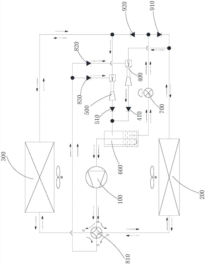
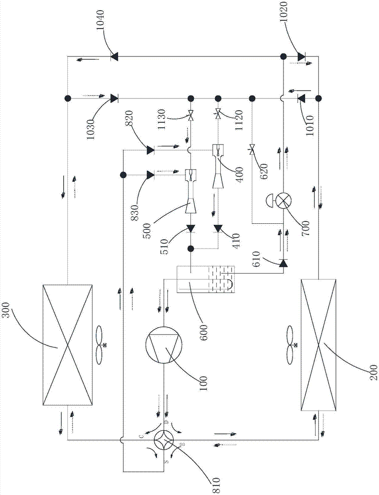
[0047] see figure 1 As shown, the heat pump system of the present invention includes a compressor 100, a first heat exchanger 200, a second heat exchanger 300, a heating ejector 400, a cooling ejector 500, a gas-liquid separator 600, a throttling device 700, a second A reversing assembly and a second reversing assembly. Wherein, the solid line arrow indicates the flow direction of the refrigerant in the heating condition, and the dotted line arrow indicates the flow direction of the refrigerant in the cooling condition.

[0048] The first port of the first heat exc...


PUM


Abstract

The invention provides a heat pump system. In a heating mode, a second reversing module communicates a second port of a first heat exchanger with an inlet of a heating sprayer, and communicates an outlet of a throttling device with a second port of a second heat exchanger; and in a refrigerating mode, the second reversing module communicates the second port of the second heat exchanger with an inlet of a refrigerating sprayer, and communicates the outlet of the throttling device with a second port of the first heat exchanger. The heating sprayer and the refrigerating sprayer are respectively designed according to the demands of heating working conditions and refrigeration working conditions, and can adapt to the demands of the heating working conditions and the refrigeration working conditions; and the heat pump system switches the heating sprayer of the refrigerating sprayer to enter a cycle through the second reversing module according to the working conditions, can respectively recover the expansion power through the heating sprayer and the refrigerating sprayer to reduce the power of a compressor, and totally improves the energy efficiency.

Description

technical field [0001] The invention relates to the technical field of temperature regulation, in particular to a heat pump system. Background technique [0002] Ejectors are used in many industries. As an effective tool for recovery of expansion work in refrigeration, ejectors can reduce the compression ratio of the compressor, increase the suction pressure, and reduce power consumption. However, since the direction of the inlet and outlet of the injector is fixed, unlike electronic throttling devices or capillary tubes, which can work in reverse, the application of the injector in the heat pump system is greatly limited. [0003] Patent application CN200980162048.X discloses the addition of ejectors to conventional heat pump systems to achieve multiple cycle controls, but the realization of cooling and heating does not rely entirely on ejectors, and the application of ejectors mainly lies in certain working conditions High-efficiency application, not the use of all workin...

Claims


Application Information

Patent Timeline
IPC IPC(8): F25B9/08F25B41/00F25B41/04F25B41/20F25B41/40
CPCF25B9/08F25B2341/0015F25B41/40F25B41/20
Inventor 黄玉优李欣叶强蔚
Owner GREE ELECTRIC APPLIANCES INC
Learn More