
Insulation method of plasma range hood

A range hood and plasma technology, applied in the direction of removing oil fume, heating method, household heating, etc., can solve the problems of greatly reduced effect, loss of dust adsorption, poor oil fume removal effect, etc., to improve the function, prolong the service life, and have a simple structure. Effect

Inactive Publication Date: 2017-09-01
NINGBO ZHENHAI YIFULAI CULTURE CREATIVE
View PDF0 Cites 1 Cited by
  • Summary
  • Abstract
  • Description
  • Claims
  • Application Information

AI Technical Summary

Problems solved by technology

[0002] The existing plasma range hood (ZL201010557216X) has a good effect of removing oil fume when it is first installed, but the effect is often reduced after being used for less than three months or half a year, and even loses the function of removing oil fume. Widely used, the root cause of the poor effect of oil fume removal is that the polar plates of the two poles are connected by current, and the plate loses the electric field and loses the function of absorbing dust, and also loses the function of removing oil fume. The location is often at the bottle shank of the porcelain joint, where it is in direct contact with the metal plate of the collector. In the process of handling and installation, if there is a little carelessness, the porcelain joint collides with the metal plate slightly, and the surface of the porcelain joint is glazed. Fine cracks will appear in the film, these cracks are invisible to the naked eye, but they will be easily broken down under a strong voltage, thus conducting the plates of the emitter and collector. Another reason is that in the high-voltage ceramic Because of the long time of use, a layer of dust or oil film will be deposited on the surface of the porcelain joint. This layer of dust or oil film will not conduct current under the voltage of 220V, but under high voltage, this layer of dust Or the oil film becomes a conductor, and as a result, the range hood loses the function of removing oil fume

Method used


Image

  • Insulation method of plasma range hood

Examples


Embodiment Construction

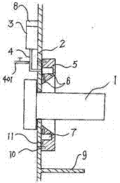
[0019] exist figure 1 Among them, the metal plate on one side of the porcelain joint 1 is installed on the housing, and an insulating plate 2 is used instead, the porcelain joint 1 is fixed on the insulating plate 2, and the air pump 3 of the air jet unit is installed on the housing. Air is supplied to the air injection disc 5 through the main pipeline 4; the main pipeline 4 of the air injection unit is connected to the air pump 3 or directly connected to the external air source pipeline 401 for delivering pressure gas, and the air injection disc 5 of the air injection unit is installed on the ceramic joint The periphery of 1 is used to set multi-directional alignment with the air injection port 6 of the porcelain joint 1;

[0020] The air injection disc of the air injection unit has an internal annular air channel 7 for containing the pressure gas supplied by the air pump; the timing device 8 is installed outside the casing for controlling the injection time period. The gas ...


PUM


Abstract

An insulation method for a plasma range hood, which is to replace the original metal plate with an insulating plate for the shell on the side where the porcelain joint is installed, so as to avoid direct contact between the porcelain joint and the metal bright body, and at the same time use spray The method is to spray air or liquid on the surface of the high-voltage porcelain joint to clean the surface of the porcelain joint, remove the hidden danger of electric conduction, keep the porcelain joint in a high insulation state, and prevent the porcelain joint from accumulating dust and condensing oil film to conduct current. The setting of the baffle not only prevents the airflow from passing through the invalid space, but also reduces the pollution of the ceramic joints by the oil and impurities brought by the airflow, thus ensuring the good smoke removal effect of the plasma range hood.

Description

technical field [0001] The invention relates to a range hood, in particular to an insulation measure for a plasma range hood, especially for the insulation of a plasma range hood suitable for removing range hoods in places with a lot of dust and thick oil fumes. Background technique [0002] The existing plasma range hood (ZL201010557216X) has a good effect of removing oil fume when it is first installed, but the effect is often reduced after being used for less than three months or half a year, and even loses the function of removing oil fume. Widely used, the root cause of the poor effect of oil fume removal is that the polar plates of the two poles are connected by current, and the plate loses the electric field and loses the function of absorbing dust, and also loses the function of removing oil fume. The location is often at the bottle shank of the porcelain joint, where it is in direct contact with the metal plate of the collector. In the process of handling and instal...

Claims


Application Information

Patent Timeline
IPC IPC(8): F24C15/20
CPCF24C15/20
Inventor 陈际军汪孟金
Owner NINGBO ZHENHAI YIFULAI CULTURE CREATIVE
Learn More