
Control method and system for hydraulic shift actuator

A shift actuator, hydraulic technology, applied in transmission control, components with teeth, belts/chains/gears, etc. The effect of improving shift control accuracy, reducing adverse effects and improving shift comfort

Active Publication Date: 2018-10-30
ANHUI JIANGHUAI AUTOMOBILE GRP CORP LTD
View PDF5 Cites 0 Cited by
  • Summary
  • Abstract
  • Description
  • Claims
  • Application Information

AI Technical Summary

Problems solved by technology

[0004] However, during the actual shifting process, due to the action of the actuator, the effect of the shifting force, and the loss of the oil pipe, the inlet pressure of the flow valve will fluctuate, resulting in an error in the oil flow output to the actuator. However, due to Constrained by the size of the detection device, installation space, and detection accuracy, the feasibility of the flow closed-loop control scheme is low, and the above-mentioned errors cannot be effectively compensated; therefore, at present, the actual control accuracy of the shift actuator is still insufficient. It is not conducive to the control of shifting speed and shifting impact, which in turn affects the comfort of shifting

Method used


Image

  • Control method and system for hydraulic shift actuator
  • Control method and system for hydraulic shift actuator
  • Control method and system for hydraulic shift actuator

Examples


Embodiment Construction

[0037] Embodiments of the present invention are described in detail below, examples of which are shown in the drawings, wherein the same or similar reference numerals designate the same or similar elements or elements having the same or similar functions throughout. The embodiments described below by referring to the figures are exemplary only for explaining the present invention and should not be construed as limiting the present invention.

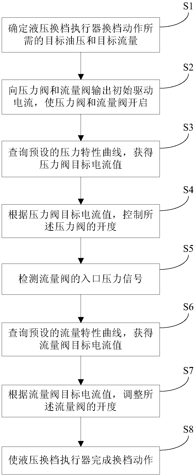
[0038] The present invention provides an embodiment of a control method of a hydraulic shift actuator, such as figure 1 As shown, it includes the following steps:

[0039] Step S1, determining the target oil pressure and target flow required for the gear shift action of the hydraulic shift actuator;

[0040] It should be noted that the shifting of the automatic transmission gearbox determines the target gear position based on the change of the accelerator pedal signal, the current vehicle speed and the current gear position. Therefore,...


PUM


Abstract

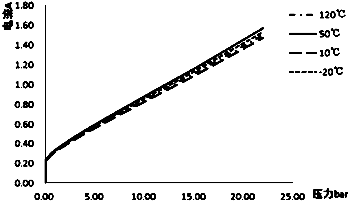
The invention discloses a control method and system of a hydraulic gear shifting executor. The method of the hydraulic gear shifting executor comprises the steps that a target oil pressure and target flow required by the gear shifting actions of the hydraulic gear shifting executor are determined; a pressure valve and a flow valve are opened through initial drive current; a preset pressure characteristic curve is inquired, and the opening degree of the pressure valve is controlled according to an inquired pressure valve target current value; inlet pressure signals of the flow valve are detected, a preset flow characteristic curve is inquired according to the inlet pressure signals of the flow valve, and then the opening degree of the flow valve is adjusted according to an inquired flow valve target current value; and finally, the hydraulic gear shifting executor completes the gear shifting actions according to the target oil pressure and target flow output by the pressure valve and the flow valve. According to the control method and system of the hydraulic gear shifting executor, flow output errors caused by inlet pressure fluctuation are remedied to a certain degree, so that the gear shifting control precision is improved, adverse effects on control over the gear shifting speed and gear shafting impact are reduced, and the gear shifting comfort is improved.

Description

technical field [0001] The invention relates to the field of transmission control of automobiles, in particular to a control method and system for a hydraulic shift actuator. Background technique [0002] The synchronizer is an important part of the automotive gear shift system. The driving methods of the gear shift actuator in the synchronizer mainly include brushed manual shift, motor drive and hydraulic drive. At present, the gear shift actuator of the synchronizer in the automatic transmission Most of them are driven by hydraulic pressure, and the working medium is oil. Therefore, the oil flow and pressure control of the gear shift actuator has a very important impact on the comfort of the car's gear shift. [0003] In the gear shifting system, the oil supply pressure is mainly controlled by the pressure control solenoid valve (referred to as the pressure valve), and the oil supply flow is controlled by the flow control solenoid valve (referred to as the flow valve), so ...

Claims


Application Information

Patent Timeline
Patent Type & Authority Patents(China)
IPC IPC(8): F16H61/02F16H61/04
CPCF16H61/0025F16H61/0265F16H61/04F16H2061/0075
Inventor 黄光颖陈伟彭邦亮
Owner ANHUI JIANGHUAI AUTOMOBILE GRP CORP LTD
Learn More