
Wheeled loader capable of being configured with travelling working machine tool

A technology of wheel loaders and tools, which is applied to earth movers/excavators, construction, etc., which can solve the problems of reducing the speed ratio coefficient of loaders, slow cleaning speed, and unclean cleaning, etc., to achieve expanded working conditions Adaptable range, simple and convenient operation, simple and reliable structure

Active Publication Date: 2017-09-01
XCMG CONSTR MACHINERY
View PDF5 Cites 2 Cited by
  • Summary
  • Abstract
  • Description
  • Claims
  • Application Information

AI Technical Summary

Problems solved by technology

When the loader is equipped with a cleaner, it often appears that the cleaning is not clean. The reason is that its walking speed and the flow rate output by the hydraulic pump to the hydraulic motor on the cleaner are in a fixed ratio, and the ratio of the tire loader is relatively large. , there will be a situation where the walking speed is faster and the cleaning speed is slower, which will lead to the phenomenon of unclean cleaning
[0005] The commonly used solution is to readjust the transmission coefficient of the gearbox and drive axle, thereby greatly reducing the walking speed of the whole machine, and then greatly reducing the ratio of the walking speed of the loader to the output flow of the hydraulic pump to the hydraulic motor on the cleaner coefficient
Although this method solves the problem that the loader is equipped with cleaners that are not cleaned cleanly, because this method reduces the maximum speed of the whole machine, it will first reduce the efficiency of the loader's transition operation; secondly, this method greatly improves The traction force of the whole machine poses a threat to the reliability of the structural parts of the whole machine

Method used


Image

  • Wheeled loader capable of being configured with travelling working machine tool
  • Wheeled loader capable of being configured with travelling working machine tool

Examples


Embodiment Construction

[0024] The following is a specific embodiment of the present invention, and the present invention will be further described in conjunction with the accompanying drawings.

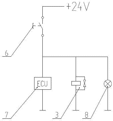
[0025] A wheel loader that can be configured with walking work tools, including a power transmission system and a hydraulic system; the power transmission system includes an engine, a hydraulic torque converter, a gearbox, and an axle; the hydraulic system includes a hydraulic oil tank 1, a hydraulic pump, and a hydraulic valve and hydraulic cylinders. Part of the energy output by the engine is transmitted to the traveling mechanism through the hydraulic torque converter and gearbox to drive the entire loader; the other part is used to drive the hydraulic cylinder through the hydraulic torque converter and hydraulic pump to realize steering and operation. ; The above are all prior art, and are not described in detail now.

[0026] combine figure 1 As shown, the hydraulic pump is a double pump 2, which inc...


PUM


Abstract

The invention discloses a wheeled loader capable of being configured with a travelling working machine tool and belongs to the technical field of engineering machinery. An engine is provided with two working curves, namely the standard working curve and the machine tool mode curve; A hydraulic pump is a double pump; an oil outlet of a main pump body is connected with a multi-channel valve connected with a machine tool motor; an oil outlet of an auxiliary pump body is connected with a solenoid valve; the solenoid valve comprises two oil outlets; and one oil outlet of the solenoid valve is connected to the multi-channel valve, and the other oil outlet of the solenoid valve is connected to a hydraulic oil tank. When an electronic control button is in a natural state, an engine ECU is in the standard working curve state, and at this time, the main pump body independently supplies oil to a whole hydraulic system; when the electric control button is pressed down, the main pump body and the auxiliary pump body jointly supply oil to the whole hydraulic system; and therefore, a flow supplied to the machine tool motor by the hydraulic pump is increased, furthermore, the travelling speed of the loader and the proportional coefficient of the flow output by the hydraulic pump of the loader to the machine tool motor are decreased, and the function of travelling working is realized.

Description

technical field [0001] The invention relates to the technical field of engineering machinery, in particular to a wheel loader. Background technique [0002] The loader is a kind of construction machinery, which is equipped with a bucket as standard, and is mainly used for loading and driving. The loader includes work linkage system, hydraulic system and power transmission system. The working linkage system includes boom, rocker arm and tie rod; the hydraulic system includes hydraulic pump, hydraulic valve and hydraulic cylinder; the power transmission system includes engine, hydraulic torque converter, gearbox and axle. Part of the energy output by the engine is transmitted to the traveling mechanism through the hydraulic torque converter and gearbox to drive the entire loader; the other part is used to drive the hydraulic cylinder through the torque converter and hydraulic pump to realize steering and loading operations. [0003] The loader can also be equipped with vario...

Claims


Application Information

Patent Timeline
Patent Type & Authority Applications(China)
IPC IPC(8): E02F9/22
CPCE02F9/22E02F9/2246
Inventor 王庆张永胜张云雷杨海英任佳璞侯璐牛宝君
Owner XCMG CONSTR MACHINERY
Learn More