Coiling machine for coiling cotton strips into cotton coils

A technology of winding machine and cotton roll, which is applied in the direction of winding mechanism, winding strip, textile and paper making, etc., can solve the problems of winding belt structure consumption and other problems, and achieve the effects of simple structure, reduced idle time and simple structure

Active Publication Date: 2017-09-01
TRUETZSCHLER GRP SE
View PDF6 Cites 2 Cited by
  • Summary
  • Abstract
  • Description
  • Claims
  • Application Information

AI Technical Summary

Problems solved by technology

Therefore, guiding the belt and maintaining a constant tension of the winding belt is structur

Method used


Image

  • Coiling machine for coiling cotton strips into cotton coils
  • Coiling machine for coiling cotton strips into cotton coils
  • Coiling machine for coiling cotton strips into cotton coils

Examples


Embodiment Construction

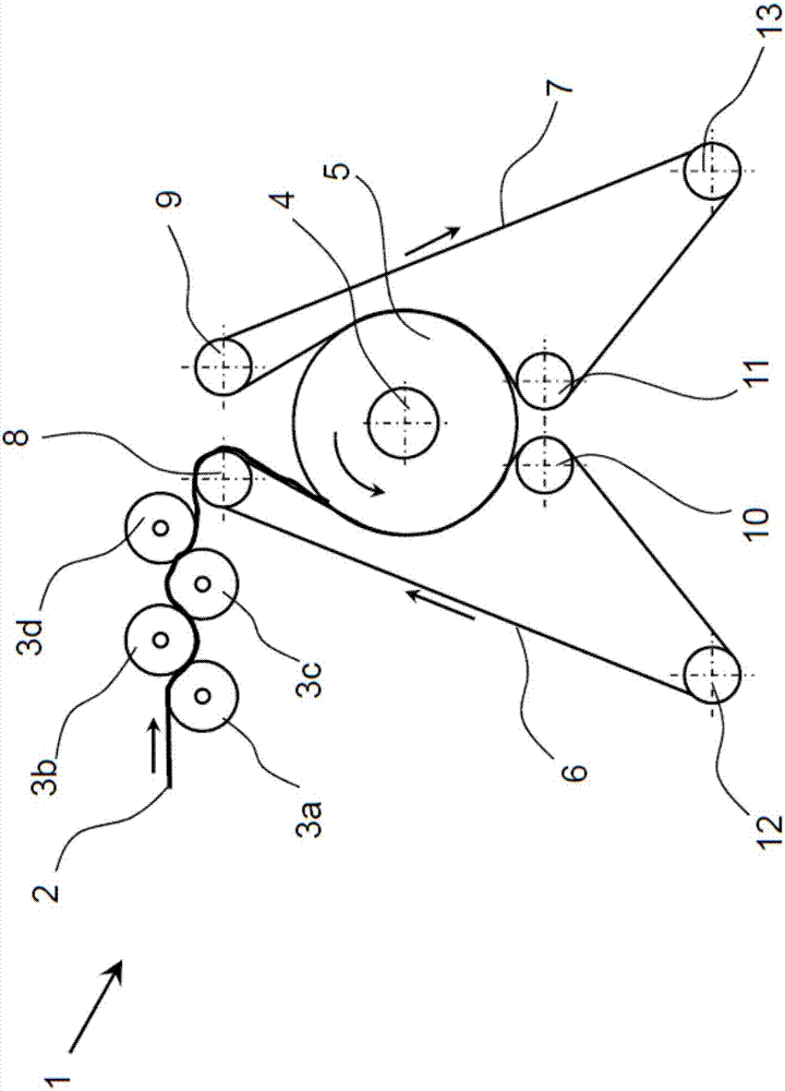
[0022] exist figure 1 In the example of 24 to 32 fiber strands, respectively, from cans (not shown) to one or two drafting devices (not shown), they are drawn there and combined in a subsequent table calender. together so that the resulting batt 2 can be made from a total of 24 to 32 slivers, which are then rolled up. The batt 2 extends in the direction of material flow (arrow) in the feed area of ​​the winder 1 to the pressure rollers 3a-3d. The batt 2 is at least partially successively surrounded by the pressure rollers 3a, 3b, 3c and 3d, between which the batt is stretched until it is picked up by the first belt 6 between the pressure rollers 3d and the deflection 8 and conveyed to the drum Tube 4 and is rolled up. In this case, the bobbin 4 can be clamped and / or guided on its end face by means of a disc, whereby the batt 3 is simultaneously guided laterally for the winding process.

[0023] The batt 2 is guided around the bobbin 4 by approximately 50° to 120° by the fir...


PUM


Abstract

The invention relates to a coiling machine and method for coiling fiber strips prepared from cotton fibers (2) to bobbins (4). The cotton fibers are led to the bobbins (4) through a continuously rounding first belt (6). The coiling machine and the method are characterized in that a continuously rounding second belt (7) leads the cotton fibers (2) along the bobbins (4).

Description

technical field [0001] The present invention relates to a winder and a method according to the preamble of claim 1 for winding a fiber strip made of batt onto a bobbin. Background technique [0002] Winding machines are known for the manufacture of laps, in which the lap is pressed against the winding rollers during the winding process with a force of up to 15.000 N (N). Very high forces are necessary in order to compress the batt to such an extent that a 300 m (meter) winding length can be wound into a lap with a diameter of approximately 550 mm (millimeters). Disadvantageously, due to the high forces, the resulting lap is stretched into the wedge shape between the rigid winding rollers and permanently deformed there. The pressure and deformation on the lap results in that the lap is heated to 40° C. (Celsius) to 60° C. and thus the cohesive substance in the cotton causes the fibrous layers to bond, which leads to increased fuzz during unwinding. The reduction in the wind...

Claims


Application Information

Patent Timeline
IPC IPC(8): D01G27/00
CPCD01G27/00B65H18/22B65H2701/177
Inventor 海因里希·特吕茨施勒托马斯·施密茨
Owner TRUETZSCHLER GRP SE
Why Eureka
Try Eureka