Water purifier having lateral concave vertical water port structure
A water purifier and nozzle technology, applied in water/sewage treatment, water/sewage treatment equipment, water/sludge/sewage treatment, etc. Inconvenience and service expenses, stable assembly quality, easy disassembly and assembly
- Summary
- Abstract
- Description
- Claims
- Application Information
AI Technical Summary
Problems solved by technology
Method used
Image
Examples
Embodiment 1
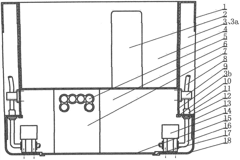
[0026] Example 1. In the accompanying drawings, the machine includes a U-shaped housing 6 with a pull-up structure 1 on both sides, an upper cover, a filter gall 2 and a water-passing control component 14; 6, and the nozzles of each filter bladder 2 are sealed and docked with the corresponding docking nozzles of the water passage in the U-shaped housing 6, and connected to the water control component 14 at the relevant place to form a filter channel, wherein the filter bladder with higher filtering accuracy is A fine gallbladder filter, which is a pre-filter channel before the fine gallbladder filter. The filter gall 2 at least adopts a filter layer structure with a closed filter shell or with an open filter cartridge and a cartridge cover structure; the water passing control component 14 is at least a water passing electric control valve or a water pressure control switch or a flow sensor Or a booster pump or a component of one of the five membrane row concentrated water flo...
Embodiment 2
[0027] Example 2. On the basis of Embodiment 1, the arched nozzle frame 18 is provided with a plug-in structure 13; the undercut facade structure 3 is provided with a matching structure corresponding to the arched nozzle frame plug-in structure 13; Surface structure 3 plug fit. The undercut facade structure 18 has two side plates 3a and a bottom plate 3b, and its cross section is a groove-shaped structure with an opening facing outward. In order to increase the matching stability of the bow-shaped nozzle frame 18, the bow-shaped nozzle frame 18 is provided with a plug-in structure 13; the side concave facade structure matching structure that is plugged with the bow-shaped nozzle frame plug-in structure 13 can be arranged on the two side plates 3a, It may also be arranged on the bottom plate 3b, or on the side plates 3a and the bottom plate 3b, or on both side plates 3a and the bottom plate 3b. With the help of one of the four above-mentioned plug-in fit structure modes, the ...
Embodiment 3
[0028] Example 3. On the basis of embodiments 1 and 2, the side plates 3a of the undercut facade structure 6 are connected to the bottom surface of the U-shaped housing 6, and the bottom surface of the bottom plate 3b and the bottom surface of the U-shaped housing 6 are non-conductive. The connection structure, that is, the lower end surface of the bottom plate 3b of the undercut facade structure is not connected to the bottom surface of the U-shaped housing 6; the bow-shaped nozzle frame 18 is connected and matched with the U-shaped housing 6 to form a U-shaped housing 6 with a closed bottom, and the two parts The surrounding internal space runs through. The purpose of adopting this structure is to make full use of the lower space of the U-shaped housing 6 as much as possible, so as to place the relevant water passing control components 14, and at the same time set the position of the fastening standard parts for fixing the bow-shaped nozzle bracket 18 as concealed as possibl...
PUM
 Abstract
Description
Claims
Application Information
 - R&D
- Intellectual Property
- Life Sciences
- Materials
- Tech Scout
- Unparalleled Data Quality
- Higher Quality Content
- 60% Fewer Hallucinations
Browse by: Latest US Patents, China's latest patents, Technical Efficacy Thesaurus, Application Domain, Technology Topic, Popular Technical Reports.
© 2025 PatSnap. All rights reserved.Legal|Privacy policy|Modern Slavery Act Transparency Statement|Sitemap|About US| Contact US: help@patsnap.com

