
Pattern preparation method and electronic equipment

A technology of electronic equipment and patterns, which is applied in the direction of electrical equipment casings/cabinets/drawers, electrical components, casings/cabinets/drawer parts, etc., can solve the problems of logo pattern falling off and logo pattern limitations, and achieve The logo pattern is firm, it is convenient for large-scale industrial application, and the process is simple.

Inactive Publication Date: 2017-09-01
LENOVO (BEIJING) LTD
View PDF7 Cites 7 Cited by
  • Summary
  • Abstract
  • Description
  • Claims
  • Application Information

AI Technical Summary

Problems solved by technology

[0002] At present, the following process is often used to make a high-gloss effect trademark Logo on the metal casing of electronic equipment, such as: making a Logo groove on the metal casing, and fixing the high-gloss effect Logo monomer to the Logo groove by dispensing Among them, the Logo pattern produced by this method has strong limitations, and the risk of the Logo pattern falling off is relatively high; therefore, a new method for preparing the Logo pattern is urgently needed to solve the above problems

Method used


Image

  • Pattern preparation method and electronic equipment
  • Pattern preparation method and electronic equipment
  • Pattern preparation method and electronic equipment

Examples


Embodiment 1

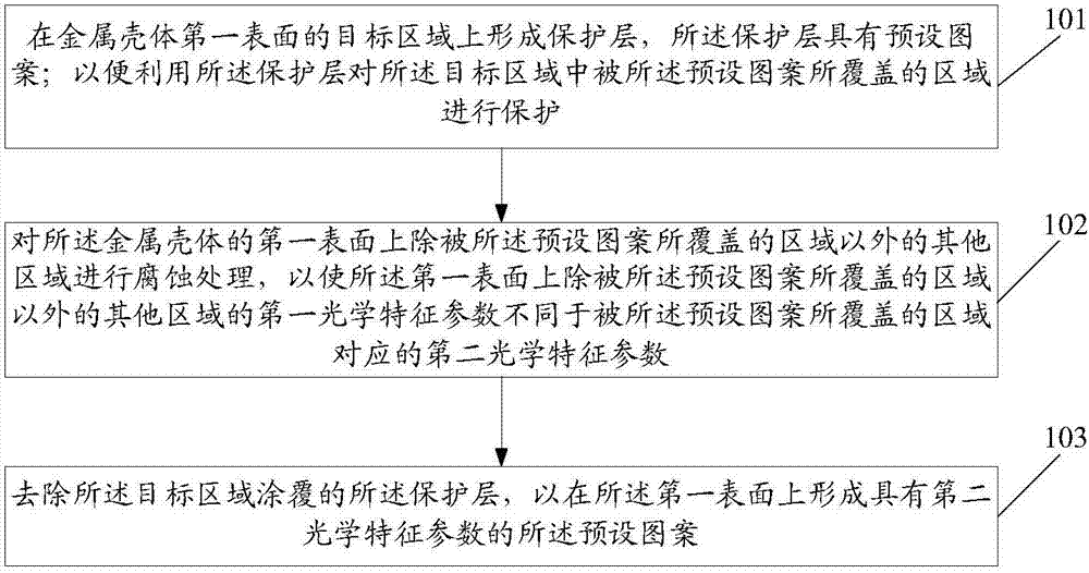
[0027] This embodiment provides a pattern preparation method, specifically, figure 1 It is a schematic flow diagram of the realization of the first pattern preparation method of the embodiment of the present invention, such as figure 1 As shown, the method includes:

[0028] Step 101: Form a protective layer on the target area of ​​the first surface of the metal shell, the protective layer has a preset pattern; so that the area covered by the preset pattern in the target area is protected by the protective layer. Protection, that is to say, using the protective layer to protect the area where the preset pattern needs to be formed.

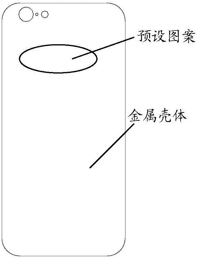
[0029] In this embodiment, the preset pattern may specifically be the pattern of the trademark Logo, that is to say, on the first surface (such as the outer surface) of the metal shell, the area where the pattern of the trademark Logo needs to be set forms a protective layer, so that , in order to use the protective layer to protect the area wher...

Embodiment 2

[0039] This embodiment provides an electronic device. The electronic device described in this embodiment may be any device with a metal casing. Further, the electronic device is at least provided with a processor capable of data processing; specifically, the The metal casing includes a pattern forming a trademark Logo, and the pattern is formed on the outer surface of the metal casing; the visual effect of the pattern is different from the visual effect of the area on the metal casing except for the pattern; The metal shell is an integrated metal plate, and the metal plate does not have a hole reserved for the Logo.

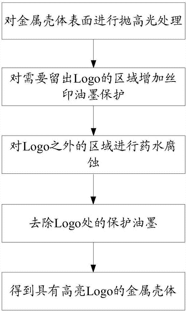
[0040] In this embodiment, the metal shell can be prepared using the following process. Specifically, first, a protective layer is formed on the target area of ​​the first surface of the metal shell, and the protective layer has a preset pattern; in order to use The protective layer protects the area covered by the preset pattern in the target area, that is to sa...


PUM


Abstract

The embodiment of the invention discloses a pattern preparation method which comprises the following steps: enabling a protection layer to be formed in a target region of a first surface of a metal shell, wherein the protection layer is provided with a predesigned pattern, and the protection layer is utilized to protect the area, covered with the predesigned pattern, in the target region; performing corrosion treatment on the other areas, excluding the area covered with the predesigned pattern, on the first surface of the metal shell, so as to enable the first optical characteristic parameter of the other areas, excluding the area covered with the predesigned pattern, on the first surface to be different from the second optical characteristic parameter corresponding to the area covered with the predesigned pattern; and removing the protection layer covering the target region, and enabling the predesigned pattern with the second optical characteristic parameter to be formed on the first surface. The embodiment of the invention further discloses electronic equipment.

Description

technical field [0001] The invention relates to pattern making technology, in particular to a pattern making method and electronic equipment. Background technique [0002] At present, the following process is often used to make a high-gloss effect trademark Logo on the metal casing of electronic equipment, such as: making a Logo groove on the metal casing, and fixing the high-gloss effect Logo monomer to the Logo groove by dispensing Among them, the Logo pattern produced by this method has strong limitations, and the risk of the Logo pattern falling off is relatively high; therefore, a new method for preparing the Logo pattern is urgently needed to solve the above problems. Contents of the invention [0003] In order to solve the existing technical problems, the embodiments of the present invention provide a pattern preparation method and an electronic device, which can at least solve the above-mentioned problems in the prior art. [0004] The technical scheme of the embo...

Claims


Application Information

Patent Timeline
Patent Type & Authority Applications(China)
IPC IPC(8): B44C1/22B44C1/00H05K5/02
CPCH05K5/0243B44C1/00B44C1/227
Inventor 吕桂林
Owner LENOVO (BEIJING) LTD
Learn More