
Special-shaped component clamping fixture

A technology of special-shaped parts and fixing clips, which is applied in the direction of clamping, positioning devices, and manufacturing tools. It can solve the problems of three-grip chucks on lathes that cannot be clamped, low production efficiency, and long auxiliary time. It achieves novel structure and fast clamping. Easy and convenient effects for range boosting, use and operation

Pending Publication Date: 2017-09-01
CHANGZHOU INST OF MECHATRONIC TECH
View PDF6 Cites 1 Cited by
  • Summary
  • Abstract
  • Description
  • Claims
  • Application Information

AI Technical Summary

Problems solved by technology

[0002] At present, in the machinery manufacturing industry, lathes and CNC lathes are widely used to process various rotating parts such as discs or shafts, but there are also many special-shaped parts that are not rotating. Chuck cannot hold
Therefore, the existing technology cannot meet its processing requirements. When positioning and clamping such parts, manual clamping is used. The labor intensity is relatively high, the auxiliary time for part processing is long, and the production efficiency is low. Therefore, it is necessary to Fixtures that can meet the clamping of special-shaped parts

Method used


Image

  • Special-shaped component clamping fixture
  • Special-shaped component clamping fixture
  • Special-shaped component clamping fixture

Examples


Embodiment Construction

[0015] In order to make the content of the present invention more clearly understood, the present invention will be further described in detail below based on specific embodiments and in conjunction with the accompanying drawings.

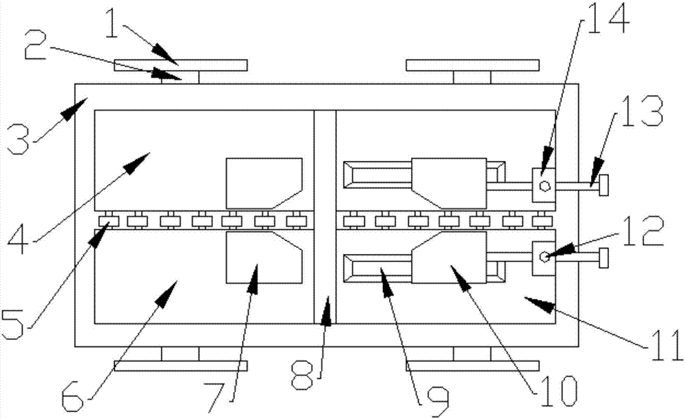
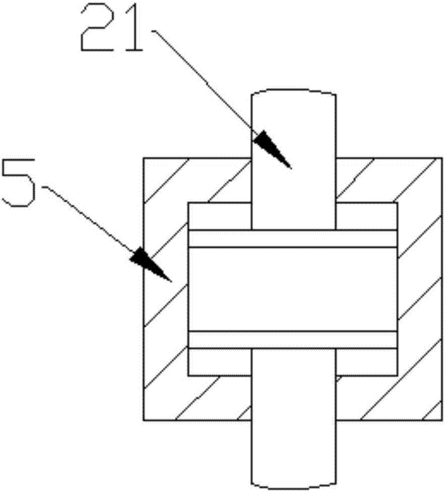
[0016] Such as Figure 1~3 As shown, a clamping fixture for special-shaped parts includes a lower template 19 and an upper template 3, a plurality of support rods 18 are welded on the upper surface of the lower template 19, and the support rods 18 play a supporting role, and the upper ends of the support rods 18 are fixed with Upper template 3, the cross section of upper template 3 is rectangular, provides installation space for the parts fixed on it, the left and right sides of upper template 3 are welded with supporting plate 17, and supporting plate 17 is used for the parts that are placed on it to support From the upper template 3, the top of the support plate 17 is provided with a movable connection block 16, and the movable connection block 1...


PUM


Abstract

A special-shaped component clamping fixture comprises a lower mold plate and an upper mold plate. A plurality of supporting rods are welded to the upper surface of the lower mold plate. The upper mold plate is fixed to the upper ends of the supporting rods. Supporting plates are welded to the left side and the right side of the upper mold plate. Movable connecting blocks are arranged on the upper portions of the supporting plates and movably connected in the lower surface of a second bottom plate. A plurality of chip removing grooves are formed in the upper surface of the middle of the second bottom plate. A fixed clamping block is fixed to the right sides of the chip removing grooves. A movable connecting plate is arranged on the right side of the fixed clamping block. A sliding block is installed in the movable connecting plate. Third bottom plates are connected to the right side of the sliding block. Sliding grooves are formed in the middles of the third bottom plates. Movable clamping blocks are movably connected in the sliding grooves. Movable threaded rods are installed at the right ends of the movable clamping blocks and penetrate through fixed blocks. The fixed blocks are welded to the upper surfaces of the third bottom plates. A plurality of telescopic connecting rods are welded to the back portion of the second bottom plate and connected into telescopic connecting blocks. The telescopic connecting blocks are arranged on the two sides of the movable connecting plate. The special-shaped component clamping fixture is good in clamping stability, convenient to operate and capable of relieving the labor intensity of workers.

Description

technical field [0001] The invention relates to a clamping fixture for special-shaped parts, which belongs to the field of clamping equipment in the machinery manufacturing industry. Background technique [0002] At present, in the machinery manufacturing industry, lathes and CNC lathes are widely used to process various rotating parts such as discs or shafts, but there are also many special-shaped parts that are not rotating. The chuck cannot be clamped. Therefore, the existing technology cannot meet its processing requirements. When positioning and clamping such parts, manual clamping is used. The labor intensity is relatively high, the auxiliary time for part processing is long, and the production efficiency is low. Therefore, it is necessary to Fixtures that can meet the clamping requirements for special-shaped parts. Contents of the invention [0003] The technical problem to be solved by the present invention is to provide a fixture for clamping special-shaped part...

Claims


Application Information

Patent Timeline
Patent Type & Authority Applications(China)
IPC IPC(8): B23Q3/06
CPCB23Q3/06B23Q3/062
Inventor 杨宏图张红党张成龙夏秋
Owner CHANGZHOU INST OF MECHATRONIC TECH
Learn More