


Quick Research
Generate reliable direction feasibility study reports for your R&D in just a few steps.

Technical Q&A
Discover and master advanced knowledge NOW. Basics, ideas, possibilities, all at once.

Find Solutions
As an expert in R&D theories, this can generate solutions to your technical problems instantly.

Evaluate Feasibility
Analyze your overall solution with one click, know your potential R&D risks in advance.

Monitor Landscape
Get weekly tech updates, stay abreast of the latest tech innovations and key insights.
Positioning method, device and system based on visible light communication
A technology of visible light communication and positioning method, which is applied in the field of device and system, positioning method based on visible light communication, can solve the problems of poor application range and low positioning accuracy, and achieve the effect of high positioning accuracy and wide application range
- Summary
- Abstract
- Description
- Claims
- Application Information
AI Technical Summary
Problems solved by technology
Method used
Image

Examples
Embodiment 1
[0044] An embodiment of the present application provides a positioning method based on visible light communication, which is used to solve the problems of low positioning accuracy and poor application range of existing mobile positioning methods.
[0045] The execution subject of the positioning method based on visible light communication provided in the embodiment of the present application may be, but not limited to, at least one of terminal devices such as a mobile phone, a tablet computer, and a personal computer (Personal Computer, PC). In addition, the execution subject of the method may also be a positioning application (Application, APP) installed on the terminal device itself.
[0046] For ease of description, the implementation of the method will be introduced below by taking the subject of execution of the method as an example of a smart phone. It can be understood that the implementation subject of the method is the smart phone is only an exemplary description, and...
Embodiment 2
[0084] Based on the foregoing embodiment 1, the inventive concept of the present application is described in detail. In order to facilitate a better understanding of the technical features, means and effects of the present application, a positioning method based on visible light communication of the present application is further described below, thus forming the present application Another embodiment of .
[0085] An embodiment of the present application provides a positioning system based on visible light communication, which is used to solve the problems of low positioning accuracy and poor application range of existing mobile positioning methods. Such as Image 6 As shown in , it is a schematic structural diagram of the positioning system provided by the embodiment of the present application, including several visible light sources and a mobile terminal.
[0086] Wherein, the visible light source is used to determine the identification corresponding to the visible light s...
Embodiment 3
[0093] An embodiment of the present application provides a positioning device based on visible light communication, which is used to solve the problems of low positioning accuracy and poor application range of existing mobile positioning methods. The specific structural diagram of the device is shown in Figure 8 As shown, it includes: an optical signal receiving unit 31 , an optical signal analyzing unit 32 and a positioning unit 33 .
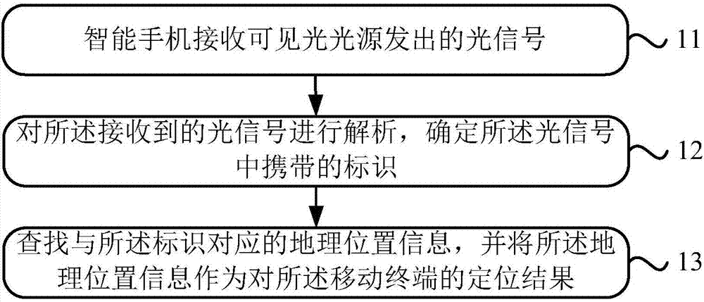
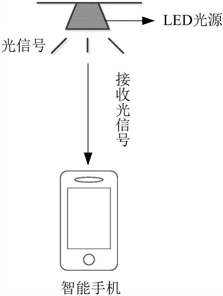
[0094] Wherein, the optical signal receiving unit 31 is configured to receive an optical signal emitted by a visible light source, wherein the optical signal carries an identification indicating the location of the visible light source;
[0095] An optical signal analysis unit 32, configured to analyze the received optical signal and determine the identifier carried in the optical signal;
[0096] The positioning unit 33 is configured to search for geographic location information corresponding to the identifier, and use the geographic locatio...
PUM
 Abstract
Description
Claims
Application Information
 - R&D Engineer
- R&D Manager
- IP Professional
- Industry Leading Data Capabilities
- Powerful AI technology
- Patent DNA Extraction
Browse by: Latest US Patents, China's latest patents, Technical Efficacy Thesaurus, Application Domain, Technology Topic, Popular Technical Reports.
© 2024 PatSnap. All rights reserved.Legal|Privacy policy|Modern Slavery Act Transparency Statement|Sitemap|About US| Contact US: help@patsnap.com