Frequency-resolved Optical Switch Method Measuring Instrument Aided by Interferometric Displacement Measurement

A frequency-resolved, optical switching technology, applied in measurement optics, measurement devices, scientific instruments, etc., can solve the problems of low precision, rising cost, inaccurate measurement results, etc., and achieve the effect of signal correction and accurate measurement

Active Publication Date: 2019-11-01
TIANJIN UNIV
View PDF1 Cites 0 Cited by
  • Summary
  • Abstract
  • Description
  • Claims
  • Application Information

AI Technical Summary

Problems solved by technology

The stepper motor has a long stroke, but the accuracy is relatively low, usually on the order of microns, but the optical period of visible light and near-infrared is 1 to 3 microns. For ultrashort pulses with only a few optical periods, the accuracy of the stepper motor Appears to be insufficient, if a high-precision stepping motor is used, the cost will increase significantly
The precision of piezoelectric ceramics is very high. By slightly adjusting the voltage, the deformation of piezoelectric ceramics can be kept. It is a good choice for precise displacement control. However, the deformation of piezoelectric ceramics is not linear, which makes it necessary to ensure that each time FROG measurements with the same step distance become very inaccurate

Method used


Image

  • Frequency-resolved Optical Switch Method Measuring Instrument Aided by Interferometric Displacement Measurement
  • Frequency-resolved Optical Switch Method Measuring Instrument Aided by Interferometric Displacement Measurement
  • Frequency-resolved Optical Switch Method Measuring Instrument Aided by Interferometric Displacement Measurement

Examples


Embodiment Construction

[0018] The technical solution of the present invention will be further described in detail below in conjunction with the accompanying drawings and specific embodiments, and the described specific embodiments are only for explaining the present invention, and are not intended to limit the present invention.
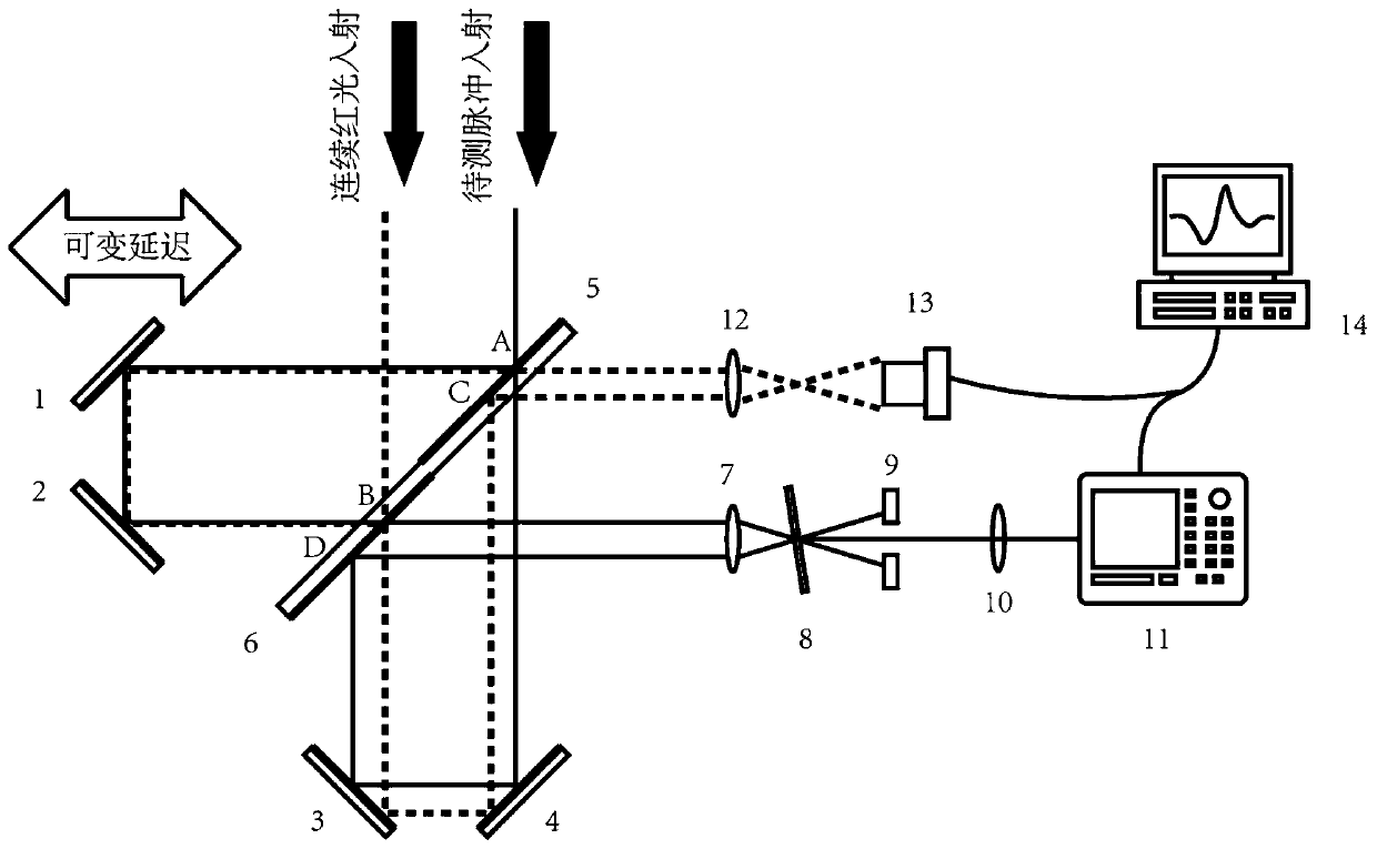
[0019] The design idea of ​​the present invention is that by injecting a beam of 658nm red light generated by a laser diode in the opposite direction at the same position as the signal light, the displacement of the boom of the Michelson interferometer can be determined by using the light and dark changes of the interference fringes of the red light. In addition, the cost of red laser diodes is very low, which avoids the large cost penalty caused by the use of advanced precision displacement components.

[0020] Such as figure 2 As shown, the present invention proposes a frequency-resolved optical switch measuring instrument assisted by interference displacement measureme...


PUM


Abstract

The invention discloses an interference displacement measurement assisted FROG (frequency-resolved optical gating) measurer, and the measurer comprises an FROG signal light path and a red light correction optical path, determines the displacement of a displacement element according to a red light interference signal, and corrects an FROG signal. The process of generating the red light interference signal is that the red light for correction arrives at a point B of a second semi-transparent semi-reflection mirror, and is divided into two beams, wherein one beam is reflected by a second total-reflection mirror and a first total-reflection mirror, and then arrives at a point A of a first semi-transparent semi-reflection mirror, and the other beam is reflected by a fourth total-reflection mirror and a third total-reflection mirror, and then arrives at a point C of the first semi-transparent semi-reflection mirror; the two beams respectively through the points A and C of the first semi-transparent semi-reflection mirror to come outwards in a parallel manner, and then enters a third lens in a parallel manner to generate a red interference signal. The measurer can be used for correcting the FROG signal, and precisely measures the deformation of the displacement element.

Description

technical field [0001] The invention relates to an ultrashort pulse measurement, in particular to a frequency resolution optical switch method measuring instrument assisted by interference displacement measurement. Background technique [0002] The time-domain pulse width and phase information of ultrashort laser pulses are important parameters of ultrashort laser pulses. Due to the extremely narrow time-domain pulse width of the femtosecond laser, the response speed of electronic devices is completely insufficient. To measure the time-domain width and phase information of the pulse, it is necessary to rely on optical methods. [0003] For the measurement of pulse phase information, frequency-resolved optical gating (FROG) is commonly used. In 1993, Trebino and others proposed the FROG method. The measured pulse is divided into two beams, one beam of light is converged on the nonlinear crystal after a time delay, and the other beam of light is scanned, and then the beam pas...

Claims


Application Information

Patent Timeline
Patent Type & Authority Patents(China)
IPC IPC(8): G01J9/02
CPCG01J9/02
Inventor 刘博文葛爱晨宋寰宇胡明列柴路
Owner TIANJIN UNIV
Why Eureka
Try Eureka