Lock nut and lock method of elastic lock nut for brake disc
A technology for anti-loosening nuts and brake discs, which is applied in the direction of nuts, screws, bolts, etc., which can solve the problems of limited application range, low installation efficiency, and limited anti-loosening degree, and achieves obvious anti-loosening effect, easy operation and extended life Effect
- Summary
- Abstract
- Description
- Claims
- Application Information
AI Technical Summary
Problems solved by technology
Method used
Image

Examples
Embodiment 1
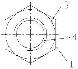
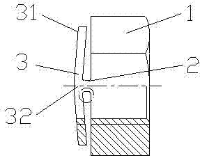
[0040] like Figure 1-Figure 3As shown, the structure of the elastic anti-loosening nut in the present invention includes a nut body 1, an anti-loosening ring 3 and a connecting block 2, and two connecting blocks 2 are arranged radially symmetrically along the upper end surface of the nut body 1; the anti-loosening ring 3 is located at Above the nut body 1, the anti-loosening ring 3 and the nut body 1 are connected into a whole through two connecting blocks 2. The anti-loosening ring 3 is centered on the connection with the two connecting blocks 2, and the two sides are inclined downward to form a direction toward the nut body. Two hypotenuses 31 in direction 1; nut body 1, connection block 2, and anti-loosening ring 3 are all provided with thread 4, the pitch of thread 4 on connection block 2 is the same as that of thread 4 on nut body 1, and the anti-loosening ring 3. The pitch of the thread 4 at the connection part 32 of the connecting block 2 is the same as the pitch of th...
specific Embodiment 2
[0048] The difference between this embodiment and the first embodiment is as follows: the pitch of the thread 4 at the midpoint of the two hypotenuses 31 of the anti-loosening ring 3 is inclined toward the direction of the nut body 1, and the pitch of the thread 4 is 0.68 times that of the thread 4 of the nut body 1.
[0049] The height of anti-loosening ring 3 is 1.5 times of thread pitch.
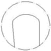
[0050] The two radial faces between the anti-loosening ring 3 and the nut body 1 on both sides of each connecting block 2 are planes, and the joints between the two ends of the plane and the anti-loosening ring 3 and the nut body 1 are rounded, like Figure 4 shown.
[0051] The height of the connection block is 1.1 times the pitch.
specific Embodiment 3
[0052] The difference between this embodiment and the above-mentioned embodiment is as follows: the pitch of the thread 4 at the midpoint of the two hypotenuses 31 of the anti-loosening ring 3 is inclined toward the direction of the nut body 1, and the pitch of the thread 4 is 0.72 times of the pitch of the thread 4 of the nut body 1 .
[0053] The height of anti-loosening ring 3 is 1 times pitch.
[0054] The two radial surfaces between the anti-loosening ring 3 and the nut body 1 on both sides of each connecting block 2 are planes, and chamfers are provided at the joints between the two ends of the plane and the anti-loosening ring 3 and the nut body 1, like Figure 5 shown.
[0055] The height of the connection block is 1.2 times the pitch.
[0056] The above-mentioned embodiment also relates to a method for preventing loosening of the elastic locking nut used for the brake disc. An anti-loosening ring is arranged on the upper end of the nut body, and the anti-loosening r...
PUM
 Abstract
Description
Claims
Application Information
 - R&D
- Intellectual Property
- Life Sciences
- Materials
- Tech Scout
- Unparalleled Data Quality
- Higher Quality Content
- 60% Fewer Hallucinations
Browse by: Latest US Patents, China's latest patents, Technical Efficacy Thesaurus, Application Domain, Technology Topic, Popular Technical Reports.
© 2025 PatSnap. All rights reserved.Legal|Privacy policy|Modern Slavery Act Transparency Statement|Sitemap|About US| Contact US: help@patsnap.com