
Reinforcing steel bar applicable to concrete

A technology of concrete and steel bars, applied to structural elements, building components, building reinforcements, etc., can solve problems such as collapse, inaccessibility, and easy release of fractures

Inactive Publication Date: 2017-08-25
江苏森林建筑新材料股份有限公司
View PDF4 Cites 1 Cited by
  • Summary
  • Abstract
  • Description
  • Claims
  • Application Information

AI Technical Summary

Problems solved by technology

The bonding coefficient of the steel bars used in the market is usually not more than 1, and such a bonding coefficient can only be said to meet the national standard, but it cannot achieve higher firm strength. When encountering disasters such as earthquakes and typhoons, Easy to release dangers such as fracture and collapse

Method used


Image

  • Reinforcing steel bar applicable to concrete
  • Reinforcing steel bar applicable to concrete
  • Reinforcing steel bar applicable to concrete

Examples


Embodiment Construction

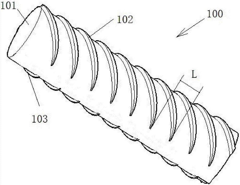
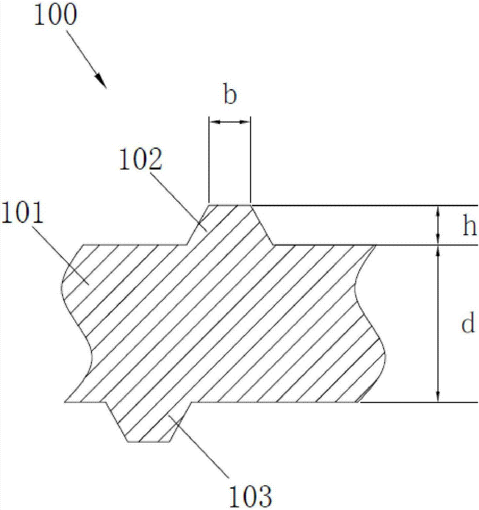
[0050] Such as figure 1 As shown, the steel bar 100 suitable for concrete includes a steel bar body 101 and several transverse ribs 102 and 103 distributed along the length direction of the steel bar body. The transverse ribs 102, 103 protrude from the steel bar body 101. is d, the maximum dimension of the transverse ribs 102, 103 protruding from the steel bar body 101 is h, and the width of the top of the transverse ribs 102, 103 protruding from the steel bar body is defined as the width b of the rib top, which corresponds to the length direction of the steel bar body 101 The distance between two adjacent transverse ribs is defined as the rib spacing L.

[0051] Such as figure 1 and figure 2 As shown, the transverse ribs are divided into two groups of transverse ribs 102 and transverse ribs 103 , which are respectively arranged on both sides of the steel bar body 101 . The portion of the reinforcing bar body 101 between the two sets of transverse ribs 102 and 103 is smoot...


PUM


Abstract

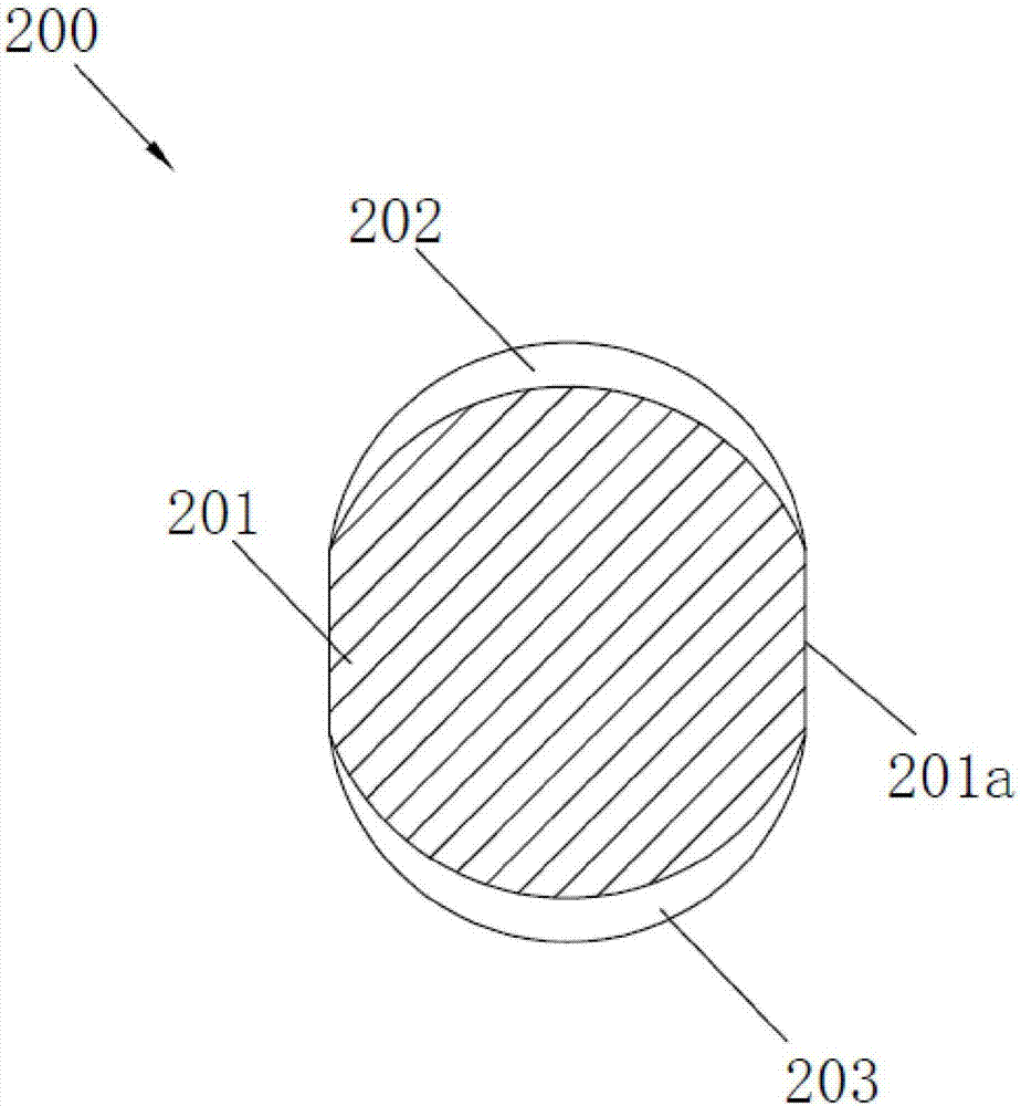
The invention discloses a reinforcing steel bar applicable to concrete, which comprises a reinforcing steel bar body and a plurality of cross ribs. The maximum size of the cross section of the reinforcing steel bar body is d, the maximum size of each cross rib projected from the reinforcing steel bar body is h, the width of the top of each cross rib projected from the reinforcing steel bar body is defined as rib top width b, and the distance between each two adjacent cross ribs in the length direction of the reinforcing steel bar body is defined as rib spacing L; the cross ribs are divided into two groups, which are respectively arranged on both sides of the reinforcing steel bar body; the parts, which are between the two groups of cross ribs, of the cross section of the reinforcing steel bar body are smooth curves or / and straight lines; the value range of the maximum size h of each cross rib projected from the reinforcing steel bar body is between 0.03d and 0.2d; the value range of the rib top width b is between 0.04d and 0.1d; and the value range of the rib spacing L is between 0.3d and 0.8d. By improving the shape and size parameters of the reinforcing steel bar, the invention ensures that the reinforcing steel bar body has a smooth external profile, a structure which has the risk of cracking is eliminated when the reinforcing steel bar is combined with concrete, and thereby the degree of firmness of reinforced concrete formed by the reinforcing steel bar is increased.

Description

technical field [0001] The invention relates to a steel bar, in particular to a steel bar suitable for concrete. Background technique [0002] Reinforced concrete is often referred to as reinforced concrete in engineering. It refers to a composite material that works together to improve the mechanical properties of concrete by adding steel mesh, steel plates or fibers to the concrete. [0003] The reason why reinforced concrete can work together is determined by its own material properties. First of all, steel bars and concrete have approximately the same linear expansion coefficient, and excessive stress will not be generated due to different environments. Secondly, there is a good bond between the steel bar and the concrete. Sometimes the surface of the steel bar is also processed into ribs with intervals (called deformed steel bar) to improve the mechanical engagement between the concrete and the steel bar. However, this is still not enough to transmit the steel bar and...

Claims


Application Information

Patent Timeline
Patent Type & Authority Applications(China)
IPC IPC(8): E04C5/03
CPCE04C5/03
Inventor 姚圣法
Owner 江苏森林建筑新材料股份有限公司
Learn More