Rectifier units for turbomachines

A technology of turbine units and rectifiers, which is applied to components of pumping devices for elastic fluids, machines/engines, mechanical equipment, etc., and can solve problems such as engulfment, gaps, and screw head separation

Active Publication Date: 2016-11-16
SN DETUDE & DE CONSTR DE MOTEURS DAVIATION S N E C M A
View PDF7 Cites 0 Cited by
  • Summary
  • Abstract
  • Description
  • Claims
  • Application Information

AI Technical Summary

Problems solved by technology

[0006] The disadvantage of this type of implementation is that over time the elastomer gradually becomes detached and void from the countersink and the screw head
Although the screw head does not intrude into the secondary flow, the secondary flow is engulfed in the countersink and creates aerodynamic disturbances

Method used


Image

  • Rectifier units for turbomachines
  • Rectifier units for turbomachines
  • Rectifier units for turbomachines

Examples


Embodiment Construction

[0045] For reasons of clarity, only elements necessary for the understanding of the invention are shown, not to scale, but only in a schematic manner. Also, phase diagram elements found in different figures have the same reference numerals.

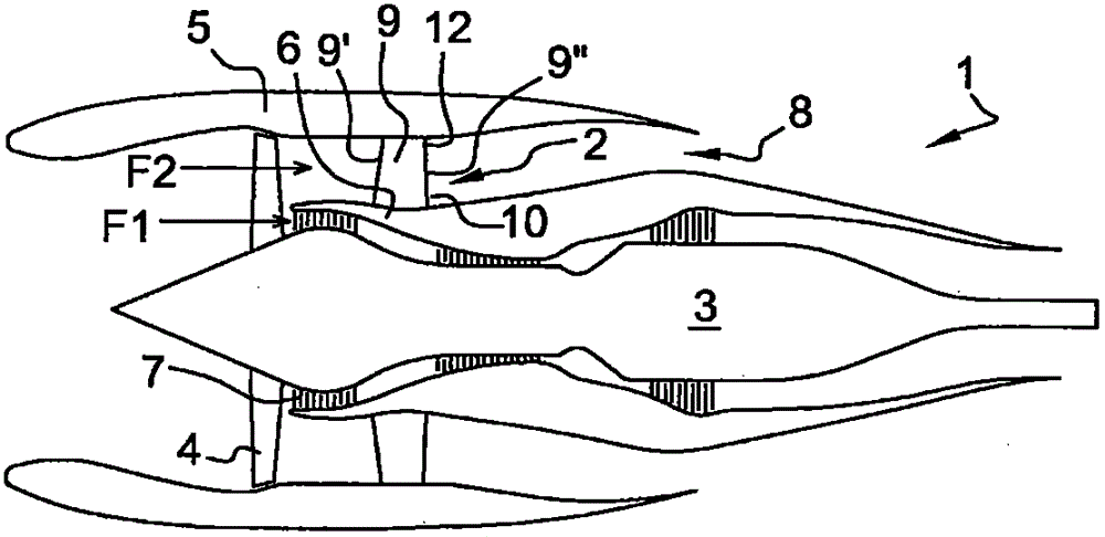
[0046] For the following description, it should be understood that the gas passes upstream of the turbojet engine (turbine block), traveling to the downstream side of the latter, each element is indicated by the reference sign "X", and the upstream side of each element is indicated by The reference "X" followed by a single prime is indicated; the downstream side of each element is indicated by the reference "X" followed by two primes.

[0047] figure 1 A schematic twin-flow turbojet engine 1 is shown. This twin-flow turbojet engine 1 notably comprises a rectifier 2 according to the invention. The turbojet engine 1 further comprises an electric motor 3 with a front mounted fan 4 surrounded by a casing ring 5 (forming the fan case in the...


PUM


Abstract

A flow straightener device for a turbomachine including an inner shell ring and an outer shell ring surrounding the inner shell ring, at least one out of the inner shell ring and outer shell ring having first orifices; at least two flow straightener vanes each including, at least at one same first end, an attachment platform having second orifices positioned facing the first orifices; the at least two vanes being assembled with at least one of the inner shell ring and outer shell ring by at least one first device of attachment introduced into the first orifices and the second orifices. The flow straightener device includes a covering platform covering the at least one first device of attachment.

Description

technical field [0001] The present invention relates to a rectifier arrangement for a turbine engine block, and more particularly for a twin-flux turbojet engine. Background technique [0002] A twin-flux turbojet engine used for aircraft propulsion usually includes an upstream fan delivering an annular airflow. This annular airflow is divided by the annular intermediate hub into a primary flow, which is supplied to the electric motor driving the fan, and a secondary flow, which is ejected in the atmosphere while providing most of the turbojet's thrust. The fan is included in a fan case that bounds the external secondary flow. [0003] Downstream of the fan, between the fan case and the intermediate hub, upstream to downstream rectifier blades are positioned to rectify the secondary flow in the motor axis, and structural arms allow the intermediate hub to be integrated with the fan case. [0004] According to an embodiment described in document EP1908923, a straightener bl...

Claims


Application Information

Patent Timeline
IPC IPC(8): F04D29/54F04D29/64F01D9/04
CPCF01D9/042F04D29/542F04D29/644Y02T50/60Y10T29/49229
Inventor 吉恩·马克·克劳德·佩罗拉兹
Owner SN DETUDE & DE CONSTR DE MOTEURS DAVIATION S N E C M A
Why Eureka
Try Eureka