Modular permanent magnetic linear motor with independent windings

A permanent magnet linear motor, modular technology, applied in the shape/style/structure of winding conductors, electrical components, electromechanical devices, etc., can solve the problems of large thrust fluctuation, low thrust density, large amount of permanent magnets, etc. Electromagnetic load, lifting thrust density, easy wiring effect

Inactive Publication Date: 2017-08-22
NANJING UNIV OF AERONAUTICS & ASTRONAUTICS
View PDF5 Cites 2 Cited by
  • Summary
  • Abstract
  • Description
  • Claims
  • Application Information

AI Technical Summary

Problems solved by technology

[0003] In order to solve the problems of low thrust density, large amount of permanent magnets and large thrust fluctuations in the existing permanent magnet synchronous linear motor, the present invention proposes a modular permanent magnet linear motor with independent windings

Method used


Image

  • Modular permanent magnetic linear motor with independent windings
  • Modular permanent magnetic linear motor with independent windings
  • Modular permanent magnetic linear motor with independent windings

Examples


Embodiment approach 1

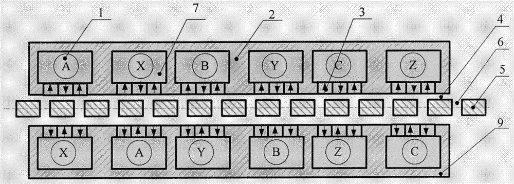
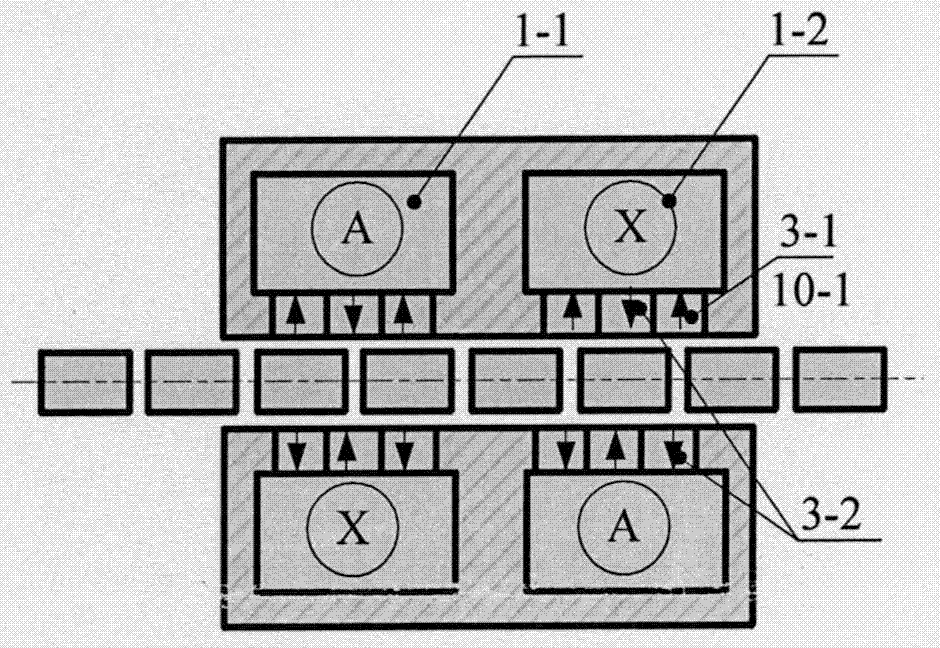
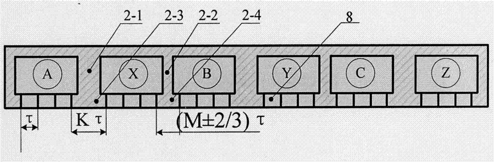
[0031] Such as figure 1 , 2 , 3, and 4 show that this embodiment is a double-sided plate type independent winding modular permanent magnet linear motor. It consists of two primary assemblies, a secondary assembly and two air gaps. A single primary assembly consists of armature winding 1 , primary core 2 and permanent magnet 3 . A large slot 7 is opened inside the primary iron core 2, and an armature winding 1 is arranged in the slot. The primary iron core 2 faces the small slot 8 of the yoke of the air gap. The number of small slots 8 is W (W is an integer, and ≥ 1), and the small slot The width of 8 is τ (τ is the pole distance). A permanent magnet 3 or a magnetically conductive core 2-5 is installed in the small slot 8, and the magnetization direction of the permanent magnet 3 is perpendicular to the direction of the air gap. For a three-phase motor, the positive winding 1-1 and negative winding 1-2 of a single effective coil of each phase are arranged in two adjacent la...

Embodiment approach 2

[0036] Such as Figure 5 , 6As shown, the difference between the present embodiment and the first embodiment is: the small slot 8 corresponding to each large slot 7 of the motor is provided with a magnetic core 2-5 and a permanent magnet 3, and the permanent magnet 3 and the magnetic core 2-5 Installed at intervals, the magnetization directions of all permanent magnets 3-1 on a single primary are the same. The number of pieces of the permanent magnet 3 under the single large slot 7 is an odd number, and the number of pieces of the magnetic guide core 2-5 is an even number. The magnetization directions of the two opposite permanent magnets on the two primary stages need to be opposite, that is, all the permanent magnets on one primary are N-pole permanent magnets 3-1, and all the permanent magnets on the other primary are S-pole permanent magnets 3-2.

[0037] With this structure, the amount of permanent magnets is halved, but the drop in thrust is small, so the cost of perma...

Embodiment approach 3

[0039] Such as Figure 7 As shown, the difference between the present embodiment and embodiments one and two is: the number of permanent magnets 3 under the single large groove 7 is an even number, and the number of pieces of the permeable magnetic core 2-5 is an odd number. The magnetization directions of all the permanent magnets 3 on a single primary are the same, and the magnetization directions of the two opposing permanent magnets on the two primary are opposite.


PUM


Abstract

The invention provides a modular permanent magnetic linear motor with independent windings and belongs to the technical field of motors. The motor comprises primary assemblies, secondary assemblies and gaps. Each primary assembly comprises an armature winding, a primary iron core and a permanent magnet structure. A big groove is arranged in each primary iron core. The armature windings are arranged in the grooves. Small grooves are arranged in faces facing inner yokes of the air gaps of the primary iron cores. The width of each small groove is tao (tao is the polar distance). The permanent magnets or magnetic conductive iron cores are installed in the small grooves. Positive and negative windings of single effective coin of each phase are arranged in adjacent two big grooves and wounded on first teeth. Teeth between different phases of windings are second teeth. The secondary assemblies consist of magnetic conductive secondary iron cores and gaps. Air gaps are formed between primary assemblies and secondary assemblies. According to the invention, by use of the design of the modular big tooth groove structure with the independent windings, harmonic waves of the even number power are reduced so that the thrust ripple is reduced; meanwhile, the lengths of ends of the windings are shortened; and the use rate of the windings is improved.

Description

technical field [0001] The invention belongs to the field of motors, in particular to a modular permanent magnet linear motor with independent windings. Background technique [0002] The direct transmission technology based on linear motors eliminates the need for intermediate complex transmission mechanisms. It has been applied in linear motion occasions such as machine tools and elevators, and its application fields are gradually expanding to various fields of production and life. However, unlike rotary motor systems, linear motor systems in most industrial applications cannot use high-speed designs to increase power density and reduce volumetric mass. Therefore, to reduce the volumetric mass of linear motors, we can only hope to increase the thrust density of the motor . Improving the thrust density of the motor can be considered from the aspects of increasing the electric load, magnetic load and magnetic field change frequency. The existing permanent magnet synchronous ...

Claims


Application Information

Patent Timeline
Patent Type & Authority Applications(China)
IPC IPC(8): H02K41/03H02K3/28
CPCH02K41/031H02K3/28H02K2213/03
Inventor 黄旭珍钱振宇李静
Owner NANJING UNIV OF AERONAUTICS & ASTRONAUTICS
Why Eureka
Try Eureka