A stator winding frame and a method for measuring the number of turns of a sub-coil

A technology of stator winding and coil turns, applied in measuring devices, measuring electrical variables, instruments, etc., can solve problems such as leakage, high hardness of thick copper wires, and scratches of copper wires, so as to improve motor performance and save skeleton materials , the effect of improving the duty cycle

Inactive Publication Date: 2011-12-14
TIANJIN SANTROLL ELECTRIC SCI & TECH
View PDF8 Cites 5 Cited by
  • Summary
  • Abstract
  • Description
  • Claims
  • Application Information

AI Technical Summary

Problems solved by technology

However, because the teeth of the block stator have edges and corners, that is, the winding circumference is approximately square, it is easy to cause the coil to be wound tightly enough and the space factor is small, especially the thick copper wire has high hardness and is inconvenient to bend, which will cause certain difficulties to production. , if the winding tension is increased, the edges and corners of the stator may also scratch the copper wire, resulting in leakage, which will affect the performance of the motor
In addition, the number of turns of the coil cannot be tested after the winding is completed, and the consistency of each stator winding cannot be ensured

Method used


Image

  • A stator winding frame and a method for measuring the number of turns of a sub-coil
  • A stator winding frame and a method for measuring the number of turns of a sub-coil
  • A stator winding frame and a method for measuring the number of turns of a sub-coil

Examples


Embodiment Construction

[0021] Embodiments of the present invention are described in further detail below in conjunction with the accompanying drawings:

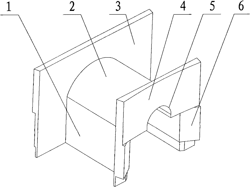
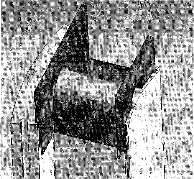
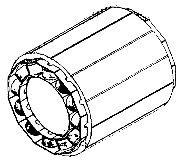
[0022] Such as Figure 1-3 Shown: 1 is the clamp arm, 2 is the winding ridge, 3 is the outer baffle, 4 is the inner baffle, 5 is the through groove, and 6 is the slope of the inner baffle.

[0023] The stator winding skeleton of the present invention includes an arc-shaped winding ridge 2 and clamp arms 1 on both sides. The winding surface of the winding ridge 2 is but not limited to an arc surface, and the distance between the clamp arms 1 on both sides depends on the width of the stator teeth. Set, just enough to buckle the stator teeth. There are inner baffles 4 and outer baffles 3 at both ends of the winding ridge 2 and the clamping wall 1, and the height of the baffles in the winding direction of the clamping arm 1 and the winding ridge 2 depends on the required winding line type and winding It depends on the number of turns, and generally t...


PUM


Abstract

The invention discloses a winding skeleton which is sleeved on the stator iron core of a motor, and a method for detecting the number of coil turns of the stator winding by using the skeleton. The winding frame includes an arc-shaped winding ridge and clamp arms on both sides, and a through hole or a through groove parallel to the clamp arm is opened on the back side of the winding surface of the winding ridge. When the frame is buckled on the stator teeth, the The through holes or slots are still open, and there are baffles at the two ends of the winding ridge and the clamping wall. The stator winding frames are used in pairs, and are respectively buckled on the stator teeth at both ends of the stator core block, and are positioned against the stator tooth tips. The fastening surface between the inner baffle plate at one end and the tooth tip of the stator is an inclined plane, and its inclination coincides with the inclined plane of the tooth tip of the stator. The winding skeleton is made of synthetic material of nylon and glass fiber. The use of the winding frame can effectively improve the space factor and winding quality of the stator winding, improve the performance of the motor, and can detect the number of coil turns of a single stator winding.

Description

technical field [0001] The invention relates to a motor winding component, in particular to a winding frame set on the stator core of a motor, and a method for detecting the number of coil turns of the stator winding by using the frame. Background technique [0002] The winding is an important part of the motor. The quality of the winding has a great influence on the performance of the motor. It is the place with the heaviest work and the weakest structure among all the structural parts of the motor. Most of the other parts of the motor are made of steel materials, which are generally less damaged under normal use. The motor winding is different, it is made of insulated wires, and the rotating magnetic field will cause the electromagnetic vibration and heat of the winding when it is energized, making the winding the most vulnerable part. In addition, improper selection of the stator and insulated wires, or misoperation of the motor and failure of the motor system protection...

Claims


Application Information

Patent Timeline
IPC IPC(8): H02K15/08G01R29/20
Inventor 王建强陈鹏
Owner TIANJIN SANTROLL ELECTRIC SCI & TECH
Why Eureka
Try Eureka