Method of forming stator coils of electric machinery
A technology of stator coils and stators, which is applied in the manufacture of motor generators, electrical components, electromechanical devices, etc., can solve the problems of motor performance degradation, magnetic loss, and decrease in duty cycle, and achieve improved duty cycle, improved performance, and low The effect of production costs
- Summary
- Abstract
- Description
- Claims
- Application Information
AI Technical Summary
Problems solved by technology
Method used
Image

Examples
no. 1 example
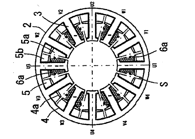
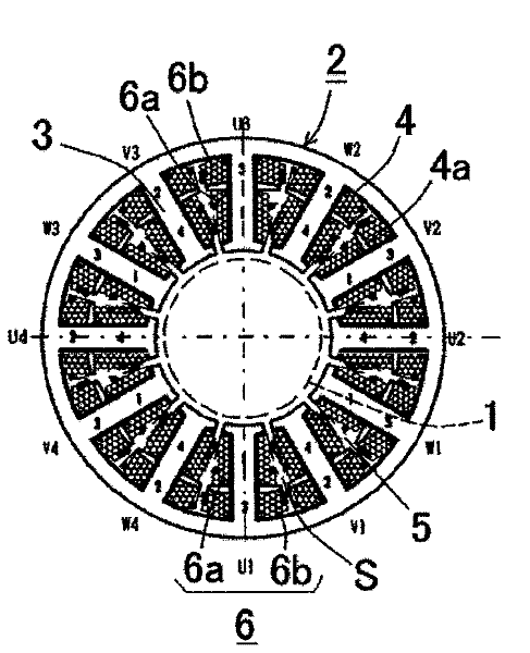
[0057] will see Figures 1A-1D etc. to describe the first embodiment of the method of the present invention. In the present embodiment, the circular stator core 2 has an even number (for example, 12) of tooth portions (magnetic pole portions) 3 protruding radially inward from the stator core 2 . A motor coil (stator coil) 6 is formed on the tooth portion 3 by winding a coil wire in multiple layers on the tooth portion 3 covered with the insulator 4 such that the coil 6 is formed in the slot 5 . The insulator 4 covering the tooth portion 3 has partition walls 4 a each dividing each slot 5 into a longitudinal inner portion (inner slot 5 a ) and a longitudinal outer portion (outer slot 5 b ). Such as Figure 5B As shown, in each slot 5, partition walls 4a protrude from the insulator 4, and a gap corresponding to a dead space S for inserting a nozzle of a wire reel (not shown) is formed between the partition walls 4a. Note that the motor coil 6 is wound in multiple layers with ...
no. 2 example
[0074] will see Figures 2A-2D etc. to describe the second embodiment of the method of the present invention. Note that the structural elements described in the first embodiment are denoted by the same reference numerals, and their explanations will be omitted.
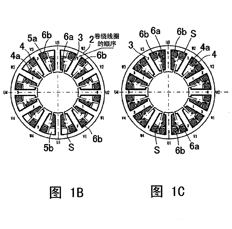
[0075] exist Figure 2A , start winding coils from V1-, U2-, W2-, V3-, U4-, and W4-phases. Insert the nozzle of the winding machine into the outer slot 5b of the slot 5 formed around the tooth portion 3 in the direction of stacking the stator cores (the direction parallel to the axial direction of the motor), so that each other is spaced in the outer slot 5b. The second coils 6b are formed one by one. That is, the second coils 6 b are provided every other in the circumferential direction of the circular stator core 2 . Note that coils can be wound starting from U1-, W1-, V2-, U3-, W3-, and V4-phases.
[0076] Such as Figure 5A and 5B As shown, in the outer slot 5b corresponding to the tooth portion 3 of the V1...
no. 3 example
[0086] will see Figure 3A-3D etc. to describe the third embodiment of the method of the present invention. Note that the structural elements described in the foregoing embodiments are denoted by the same reference numerals, and their explanations will be omitted.
[0087] exist Figure 3A Among them, coils are wound from teeth 3 of V1-, U2-, W2-, V3-, U4-, and W4-phases. Insert the nozzle of the winding machine into the outer slot 5b of the slot 5 formed around the tooth portion 3 in the direction of stacking the stator cores (the direction parallel to the axial direction of the motor), so that each other is spaced in the outer slot 5b. The second coils 6b are formed one by one. That is, the second coils 6 b are provided every other in the circumferential direction of the circular stator core 2 . Note that coils can be wound starting from U1-, W1-, V2-, U3-, W3-, and V4-phases.
[0088] exist Figure 3A , 16T coil wire is wound in the U2- and U4-phase outer slots 5b. N...
PUM
 Abstract
Description
Claims
Application Information
 - R&D
- Intellectual Property
- Life Sciences
- Materials
- Tech Scout
- Unparalleled Data Quality
- Higher Quality Content
- 60% Fewer Hallucinations
Browse by: Latest US Patents, China's latest patents, Technical Efficacy Thesaurus, Application Domain, Technology Topic, Popular Technical Reports.
© 2025 PatSnap. All rights reserved.Legal|Privacy policy|Modern Slavery Act Transparency Statement|Sitemap|About US| Contact US: help@patsnap.com