Exhaust gas purification device for internal combustion engines
A technology of exhaust gas purification device and internal combustion engine, which is applied to exhaust devices, mufflers, mechanical equipment, etc., can solve the problems of maintaining parts wind erosion, particulate matter dust leakage, etc., and achieves excellent filter function and excellent exhaust gas purification performance.
- Summary
- Abstract
- Description
- Claims
- Application Information
AI Technical Summary
Problems solved by technology
Method used
Image
Examples
no. 1 Embodiment approach
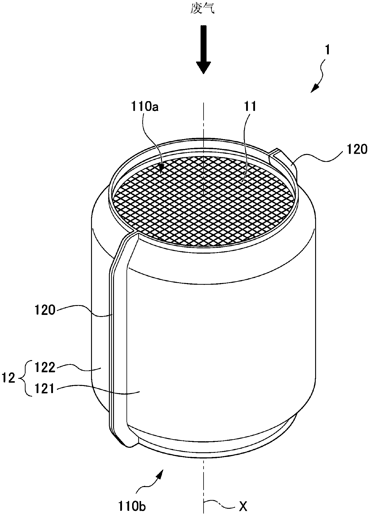
[0039] figure 1 It is a perspective view of the exhaust gas purification device of an internal combustion engine according to the first embodiment of the present invention. The exhaust gas purification device 1 of an internal combustion engine of the present embodiment is installed in an exhaust pipe of a gasoline engine (hereinafter referred to as "engine"), which is an internal combustion engine, not shown, and is opposed to the exhaust gas flowing through the exhaust pipe. A gasoline particulate filter (hereinafter, referred to as "GPF") that captures particulate matter (hereinafter referred to as "PM") or dust (Ash) of incombustible components.
[0040] The exhaust gas purifying device 1 is installed in an exhaust pipe extending downward along a side surface of the engine on the vehicle front side directly below an engine not shown. That is, the exhaust gas purification device 1 is installed in the exhaust pipe in a state where the flow direction of the exhaust gas faces down...
no. 2 Embodiment approach
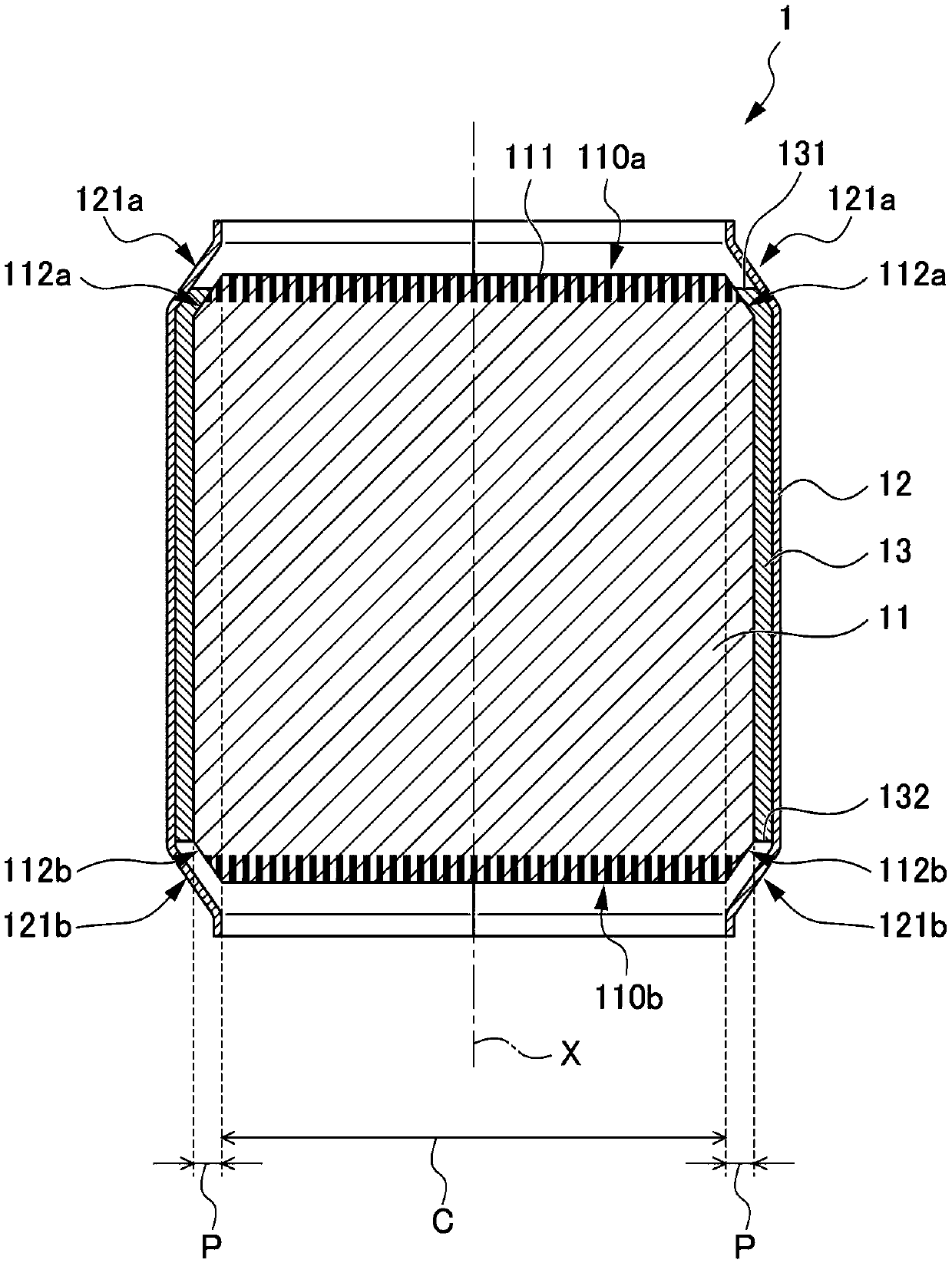
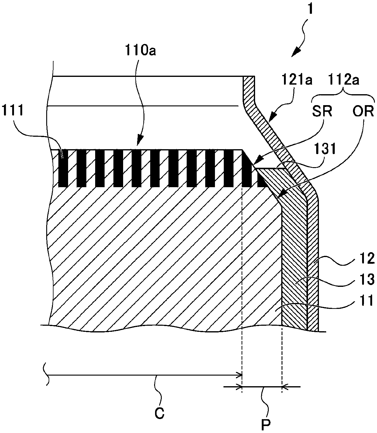
[0082] Figure 4 It is an axial cross-sectional view of the exhaust gas purification device 2 of the second embodiment of the present invention. and, Figure 5 Yes Figure 4 An enlarged view of the outer peripheral part on the downstream side in the middle.
[0083] As that Figure 4 with Figure 5 As shown, compared with the first embodiment, the exhaust gas purification device 2 of the second embodiment adopts the same structure as the first embodiment except that the structure of the outer peripheral portion P is opposite to the upstream side and the downstream side. That is, in the present embodiment, the holding member 23 is arranged such that the position of the downstream end 232 of the holding member 23 in the central axis X direction overlaps with the position of the sealing area SR in the downstream inclined portion 212b in the central axis X direction. .
[0084] The exhaust gas purification device 2 of this embodiment is manufactured by the same manufacturing method as...
no. 3 Embodiment approach
[0089] Image 6 It is an enlarged view of the upstream side outer peripheral part in the axial cross-sectional view of the exhaust gas purification device 3 of the third embodiment of the present invention. Figure 7 This is a view of the honeycomb carrier 31 of the exhaust gas purification device 3 of the third embodiment viewed from the upstream side. Figure 8 It is a perspective view of the upstream outer peripheral part of the honeycomb carrier 31 of the exhaust gas purification device 3 of the third embodiment.
[0090] Compared with the first embodiment, the exhaust gas purification device 3 of the third embodiment adopts the same structure as the first embodiment except that the structure on the upstream side of the outer peripheral portion P and the structure on the upstream side of the housing member 32 are different.
[0091] Such as Figure 6 to Figure 8 As shown, the honeycomb carrier 31 of the present embodiment is formed with a linear portion 313 extending in the dire...
PUM
 Abstract
Description
Claims
Application Information
 - R&D
- Intellectual Property
- Life Sciences
- Materials
- Tech Scout
- Unparalleled Data Quality
- Higher Quality Content
- 60% Fewer Hallucinations
Browse by: Latest US Patents, China's latest patents, Technical Efficacy Thesaurus, Application Domain, Technology Topic, Popular Technical Reports.
© 2025 PatSnap. All rights reserved.Legal|Privacy policy|Modern Slavery Act Transparency Statement|Sitemap|About US| Contact US: help@patsnap.com


