ld pin automatic closing device

An automatic technology for pins, applied in metal processing equipment, welding equipment, manufacturing tools, etc., can solve problems such as defective products, gold and tin damage, time-consuming and labor-intensive problems, and achieve exquisite design, high reliability, and no impact on output Effect

Active Publication Date: 2019-11-15
GUANGDONG RUIGU OPTICAL NETWORK COMM CO LTD
View PDF5 Cites 0 Cited by
  • Summary
  • Abstract
  • Description
  • Claims
  • Application Information

AI Technical Summary

Problems solved by technology

Laser devices in the optical communication industry have connecting pins for conductive welding. During the assembly and testing of parts, care should be taken to protect the pins to avoid breakage and damage to the gold and tin on the surface. During the capping process, the tube holder needs to be placed Into a copper electrode with an inner hole diameter of 4mm, when the 4 or 5 wire pins of the tube base come into the outer eight, during the placement process, the pins will touch the copper electrode. When the material is lowered and unloaded, the pins will be bent and deformed, resulting in defective products and scrapping
This kind of defect rate is about 3%, which is a headache for the industry. However, it is time-consuming and labor-intensive to detect and correct the outer pins manually, and there are often missed detections.

Method used


Image

  • ld pin automatic closing device
  • ld pin automatic closing device
  • ld pin automatic closing device

Examples


Embodiment Construction

[0018] The present invention will be described in further detail below in conjunction with the embodiments and with reference to the accompanying drawings.

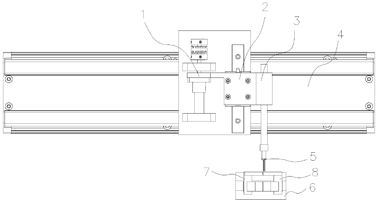
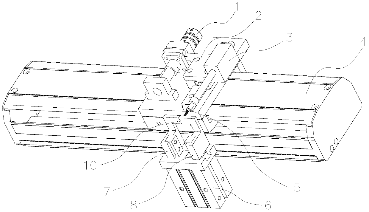
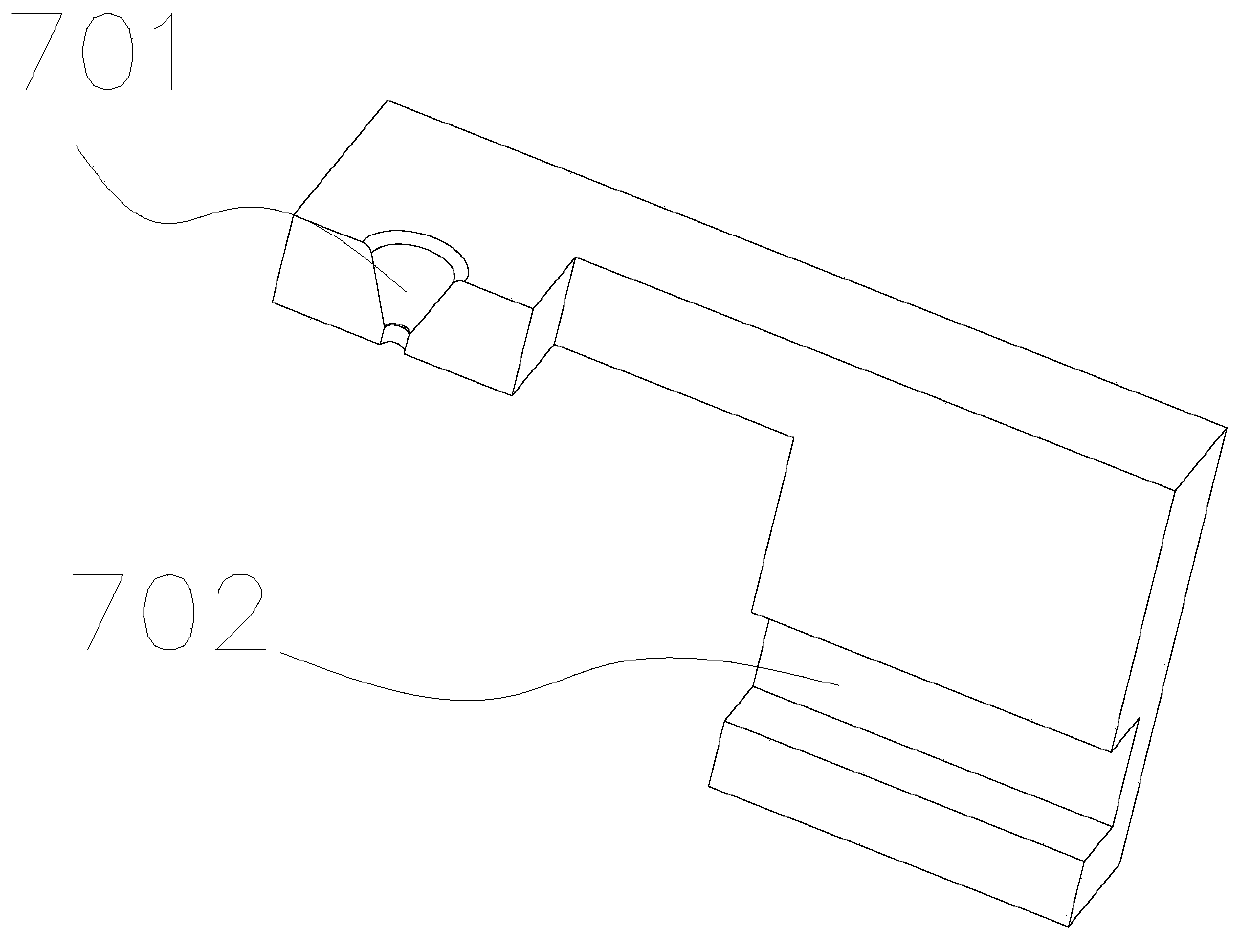
[0019] An LD pin automatic closing device, refer to figure 1 , including a closing clip arranged on the top of the copper electrode (not shown in the figure), the closing clip includes a left clip 7 and a right clip 8 driven by a pneumatic claw 6 to close or open, and the closing clip is provided with a The upper part is a cone-shaped through-hole 10, and the lower part is a cylindrical through-hole 10. The through-hole 10 is composed of the half-hole 701 on the left clip and the half-hole 801 on the right clip, which are respectively oppositely arranged, and are combined under the drive of the pneumatic claw 6. There is a Z-axis drive module 1 above the clip, and the Z-axis drive module 1 drives the suction nozzle module 3 connected to it to move up and down. The nozzle module 3 is vertically adsorbed with the tube base ...


PUM


Abstract

The invention discloses an LD pipe foot automatic closing device. The LD pipe foot automatic closing device comprises a closing clamp arranged above a material bearing table. The closing clamp comprises a left clamp body and a right clamp body which are driven by a pneumatic jaw to close or open. A through hole with the taper cylindrical upper portion and the cylindrical lower portion is formed in the closing clamp. The through hole is formed by combining half holes which are oppositely formed in the left clamp body and the right clamp body in the mode that the half holes are driven by the pneumatic jaw to close. A Z-axis driving module is arranged above the closing clamp and connected with a suction nozzle module arranged above the Z-axis driving module in a transmission mode to move up and down. A pipe seat is arranged below the suction nozzle module in a vertical adsorbing mode. The pipe foot of the pipe seat is vertically downward, when the suction nozzle module moves above the pneumatic jaw, the suction nozzle module moves downwards through the Z-axis driving module, and the pipe foot adsorbed on the suction nozzle module penetrates through the through hole; and when the suction nozzle module moves downwards, the axis of the pipe seat is overlapped with the axis of the through hole. The LD pipe foot automatic closing device has the advantages that the finished product ratio of products can be increased in the cap sealing working process.

Description

technical field [0001] The invention relates to the field of LD processing, in particular to an automatic closing device for LD pins which can greatly improve the product yield in the capping process. Background technique [0002] LD (semiconductor laser) has many advantages such as high efficiency, long life, good beam quality, small size, light weight, and full curing. It has developed rapidly in recent years and has become the most interesting research hotspot in the laser field in the world today. Laser devices in the optical communication industry have connecting pins for conductive welding. During the assembly and testing of parts, care should be taken to protect the pins to avoid breakage and damage to the gold and tin on the surface. During the capping process, the tube holder needs to be placed Into a copper electrode with an inner hole diameter of 4mm, when the 4 or 5 wire pins of the tube base come into the outer eight, during the placement process, the pins will ...

Claims


Application Information

Patent Timeline
Patent Type & Authority Patents(China)
IPC IPC(8): B23K26/70
CPCB23K26/702
Inventor 代克明曾林波肖华平
Owner GUANGDONG RUIGU OPTICAL NETWORK COMM CO LTD
Why Eureka
Try Eureka