
Self-test method for railway braking system

A braking system, functional technology, applied in the field of freight train braking system, to achieve the effect of reducing time and reducing train ready time

Active Publication Date: 2019-09-27
KNORR BREMSE RAIL SYST UK LTD
View PDF6 Cites 0 Cited by
  • Summary
  • Abstract
  • Description
  • Claims
  • Application Information

AI Technical Summary

Problems solved by technology

For trains where a self-test of multiple system components must be performed sequentially, the self-test may take up to 30 minutes (train ready)

Method used


Image

  • Self-test method for railway braking system
  • Self-test method for railway braking system

Examples


Embodiment Construction

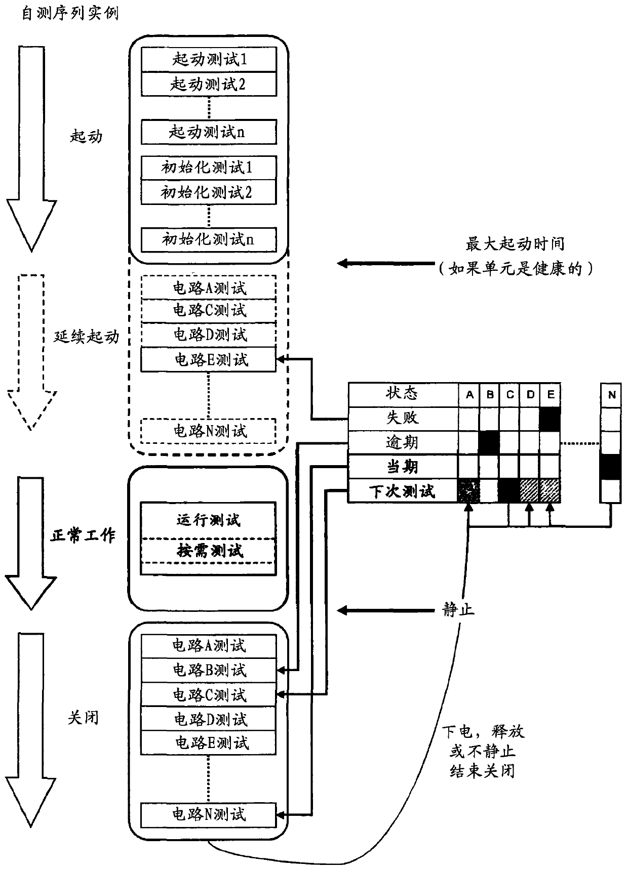
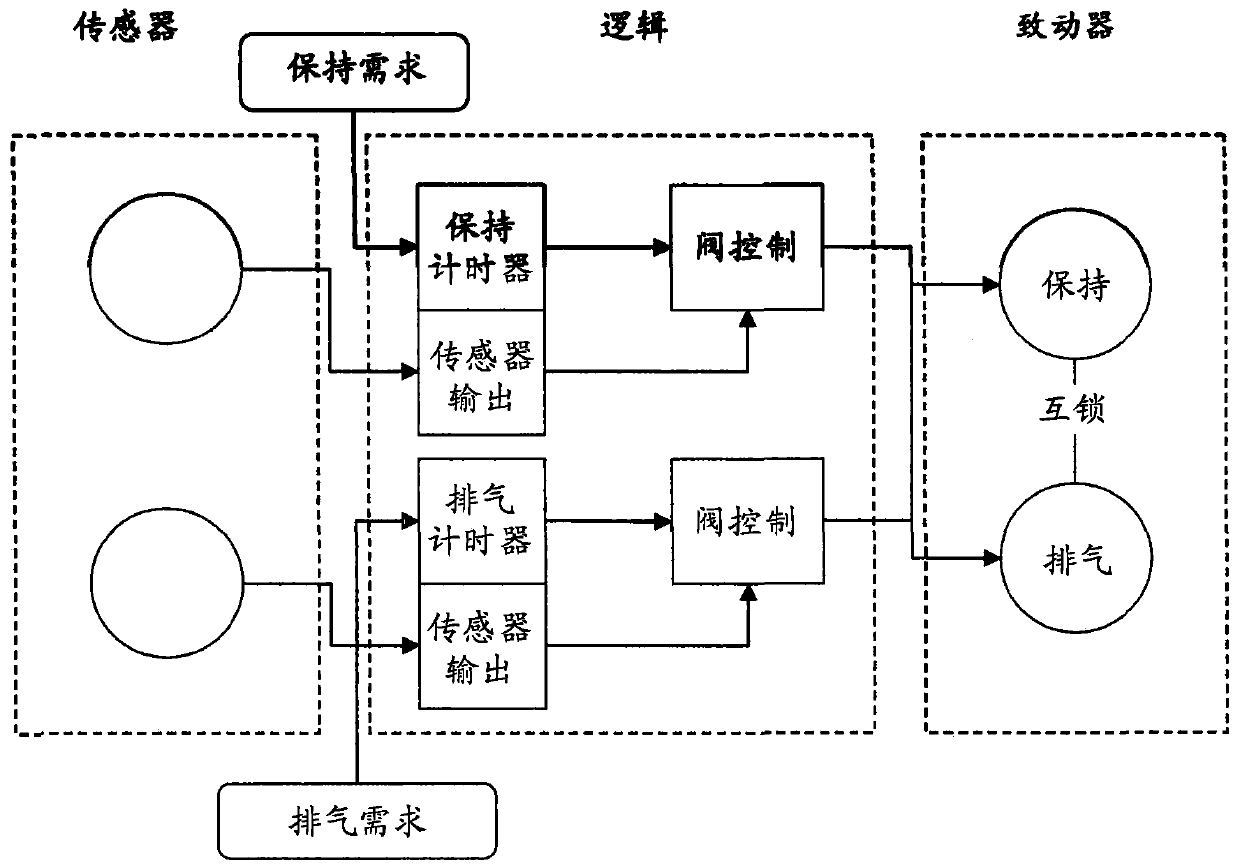
[0017] A railroad brake system for freight trains includes a main brake pipe in fluid communication with a brake distributor that is fluidly connected via conduits to relay valves that are each connected to The corresponding relief valves, which are connected to the respective brake cylinders. The brake distributor will typically have integral relay valve capability. Usually there is one relay and one relief valve per bogie, or one relief valve per axle. It is also known to use variable load valves instead of relay valves.

[0018] An auxiliary reservoir is provided which is in fluid communication with the brake distributor via the first outlet and in fluid communication with the respective relay valves via the second outlet. Auxiliary reservoir pressure is protected by a check valve in the distributor. In use, the auxiliary reservoir stores energy in the form of compressed air for applying the brakes. Use the air supply in the brake line to fill the auxiliary reservoir. ...


PUM


Abstract

A brake system has prime functions involving active control of equipment by a brake ECU, which brake ECU comprises a microcontroller and a non-volatile memory. The non-volatile memory is adapted to store the result of tests on the safety circuits carried out during, before or after operation of the brake system, the result of the tests being assigned one of at least two statuses, at least one of the said statuses being indicative of an unhealthy test. At start-up of the brake system self-tests are carried out on the circuits or components of the brake system for which an unhealthy status has been stored in the non-volatile memory, thereby enabling the brake system to operate prime functions without prior self-test.

Description

technical field [0001] The present invention relates to a self-test method (procedure, program) for railway braking systems, in particular but not exclusively for freight train braking systems. Background technique [0002] When the train is powered on, for safety reasons, a preliminary test is required to ensure the safety of the train. Multiple systems are checked, including the braking system. [0003] In braking systems, functions are divided into primary and secondary functions. The primary function is considered to be that of the braking system, which includes the active control of equipment fitted with the braking system. Included in the main functions will be any diagnostic activities necessary to ensure the safe operation of the functions. A secondary function is a function provided by the braking system which does not affect the operation of the equipment to which the braking system is attached. Secondary functions can typically provide additional information o...

Claims


Application Information

Patent Timeline
Patent Type & Authority Patents(China)
IPC IPC(8): B60T13/66B60T17/22
CPCB60T13/665B60T17/221B60T17/228B60T7/12B60T2270/406
Inventor N·安斯特
Owner KNORR BREMSE RAIL SYST UK LTD
Learn More