
Multi-charge-pump system capable of optimizing power consumption

A pump system and multi-charge technology, applied in the direction of output power conversion devices, electrical components, high-efficiency power electronics conversion, etc., can solve the problems of clock drive module BUF and coupling capacitor C waste, etc., to optimize power consumption and reduce total demand , The effect of reducing power consumption

Inactive Publication Date: 2017-08-18
SHANGHAI HUALI MICROELECTRONICS CORP
View PDF6 Cites 0 Cited by
  • Summary
  • Abstract
  • Description
  • Claims
  • Application Information

AI Technical Summary

Problems solved by technology

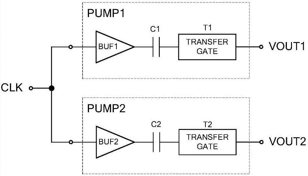
In order to meet the load requirements of the two charge pumps in all modes, the design index (SPEC) of each charge pump needs to be able to meet the maximum load conditions in different modes, that is, VOUT1 design load = max{3,1,3} =3; VOUT2 design load=max{1,4,0}=4, therefore, the whole system needs to be designed to achieve a design load of 3+4=7, usually the design load is positively correlated with the driving clock and coupling capacitor, so correspondingly 3 +4=7 units of clock drive module BUF and coupling capacitor C, but in fact, the load sum of the two charge pumps is only 5 in the maximum load mode MODE2, that is, only 5 units of clock drive module BUF and coupling capacitor C are required, the minimum In mode MODE3, the load sum of the two charge pumps is only 3, that is, only 5 units of clock drive module BUF and coupling capacitor C are needed, and the total clock drive module BUF and coupling capacitor C of the two charge pumps are designed to be 7 units, resulting in clock drive Waste of module BUF and coupling capacitor C in some application modes

Method used


Image

  • Multi-charge-pump system capable of optimizing power consumption
  • Multi-charge-pump system capable of optimizing power consumption

Examples


Embodiment Construction

[0024] The implementation of the present invention will be described below through specific examples and in conjunction with the accompanying drawings, and those skilled in the art can easily understand other advantages and effects of the present invention from the content disclosed in this specification. The present invention can also be implemented or applied through other different specific examples, and various modifications and changes can be made to the details in this specification based on different viewpoints and applications without departing from the spirit of the present invention.

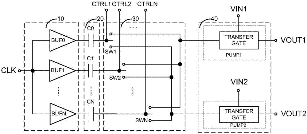
[0025] figure 2 It is a circuit structure diagram of a multi-charge pump system with optimized power consumption in the present invention. like figure 2 As shown, the present invention is a multi-charge pump system for optimizing power consumption, including: a clock drive module 10 , a coupling capacitor module 20 , a controllable switch module 30 and a one-way transmission gate mo...


PUM


Abstract

The invention discloses a multi-charge-pump system capable of optimizing power consumption. The multi-charge-pump system comprises a clock driving module, a coupling capacitor module, a controllable switch module, and a one-way transmission gate module, wherein the clock driving module is used for dividing a clock input signal into multiple paths to increase driving capability thereof; the coupling capacitor module is used for coupling voltage change of a clock driven by the clock driving module to the input end of the controllable switch module; the controllable switch module is used for connecting the multiple paths of clock voltage changes transmitted by the coupling capacitor module to the clock input end of the one-way transmission gate module under control of multiple control signals; and the one-way transmission gate module is used for converting the clock alternating current voltage output by the controllable switch module into one-way direct current to be output. By virtue of integration of module circuits with same functions and structures of each charge pump, and allocation to corresponding output charge pumps according to requirements, the total requirement on clock driving sub circuits and the coupling capacitor is lowered, and lowering of power consumption is realized.

Description

technical field [0001] The invention relates to a multi-charge pump system, in particular to a multi-charge pump system with optimized power consumption. Background technique [0002] figure 1 Shown is a multi-charge pump system with two charge pumps PUMP1 and PUMP2, each of which has an independent clock drive module BUF1 / BUF2, coupling capacitor C1 / C2 and one-way transmission gate (TRANSFER GATE) T1 / T2, The clock drive modules BUF1 / BUF2 and coupling capacitors C1 / C2 of different charge pumps have the same structure but may have different sizes, but the one-way transmission gate (TRANSFER GATE) T1 / T2 usually has a different structure, and all charge pumps PUMP1 / PUMP2 use the same The clock signal CLK, VOUT1 and VOUT2 are outputs of different charge pumps. [0003] Table 1 exemplifies the respective load levels of VOUT1 and VOUT2 in different application modes MODE1, MODE2, and MODE3 of the multi-charge pump system. In order to meet the load requirements of the two charge...

Claims


Application Information

Patent Timeline
IPC IPC(8): H02M3/07
CPCH02M3/07H02M1/0003H02M1/0048H02M1/007Y02B70/10
Inventor 金建明
Owner SHANGHAI HUALI MICROELECTRONICS CORP
Learn More