
Coupling inversion structure of dielectric waveguide filter

A dielectric waveguide and filter technology, applied in the field of dielectric waveguide filters and their coupling inversion structures, can solve the problems of weak cross-coupling strength, difficult process, low efficiency, etc., achieve simplified structure, reduce assembly tolerance, and improve production accuracy Effect

Active Publication Date: 2017-08-18
SHENZHEN SAMSUNG COMM TECH RES +1
View PDF4 Cites 12 Cited by
  • Summary
  • Abstract
  • Description
  • Claims
  • Application Information

AI Technical Summary

Problems solved by technology

The existing technical problems are: on the one hand, the parts of the product are increased, which is cumbersome in assembly and fixing, and the efficiency is low
On the other hand, the cross-coupling provided by this structure is weak and difficult to strengthen, which further increases the difficulty of design
[0006] The third solution is the coupling polarity reversal scheme of the window. The technical problem is that different dielectric blocks need to be welded together, which is difficult in the process and is not conducive to cost control.

Method used


Image

  • Coupling inversion structure of dielectric waveguide filter
  • Coupling inversion structure of dielectric waveguide filter
  • Coupling inversion structure of dielectric waveguide filter

Examples


Embodiment Construction

[0027] The technical solutions in the embodiments of the present invention will be clearly and completely described below in conjunction with the accompanying drawings in the embodiments of the present invention. Obviously, the described embodiments are only some, not all, embodiments of the present invention. Based on the embodiments of the present invention, all other embodiments obtained by persons of ordinary skill in the art without creative efforts fall within the protection scope of the present invention.

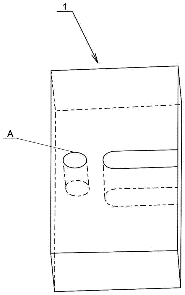
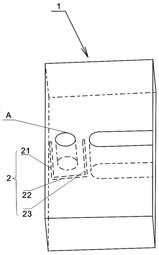
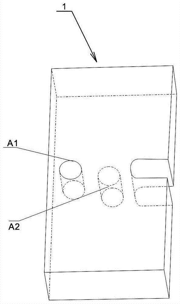
[0028] see Figure 1-Figure 2 Shown is Embodiment 1 of the coupling inversion structure of the dielectric waveguide filter provided by the present invention. The coupling inversion structure of the dielectric waveguide filter in this embodiment includes:

[0029] The resonator 1 has a dielectric block, the surface of the dielectric block is covered with a conductive layer, at least one hole structure is opened on the surface of the resonator 1, and the continuous di...


PUM


Abstract

The embodiment of the invention provides a coupling inversion structure of a dielectric waveguide filter. At least one hole structure is formed in a resonator and a continuous dielectric widow is formed in the resonator along the periphery of the hole structure, so that the dielectric of the resonator can be exposed to realize coupling between resonators. The length dimension of the dielectric window is set to exceed the half wavelength of the operating frequency of the dielectric waveguide filter so as to realize coupling polarity inversion of the resonator. In addition, the invention also discloses a dielectric waveguide filter. With the dielectric waveguide filter and the coupling inversion structure thereof, coupling polarity inversion between resonators can be realized without welding, the negative coupling is generated, and the assembling tolerance caused by welding is reduced; the production precision is improved; and integrated production of dielectric filters can be realized.

Description

technical field [0001] The invention relates to a radio frequency filter, in particular to a dielectric waveguide filter and its coupling inversion structure. Background technique [0002] With the development of the filter industry, miniaturization and light weight have gradually become a trend. The dielectric waveguide can greatly reduce the size of the product, and has the advantages of high Q value and small temperature drift. It is a good miniaturization solution. [0003] The current dielectric waveguide filter and cavity filter still have the technical problems of complex cross-coupling (negative coupling) structure, inflexibility, and difficult implementation. For example: the existing dielectric waveguide filters that generate cross-coupling mainly have the following three forms: [0004] The first is the solution of the metal probe structure, which can generate negative cross-coupling. During implementation, the medium needs to be punched, and then the metal pro...

Claims


Application Information

Patent Timeline
IPC IPC(8): H01P1/20H01P7/10
CPCH01P1/2002H01P7/10
Inventor 康海聚
Owner SHENZHEN SAMSUNG COMM TECH RES
Learn More