
An Integrated Video Surveillance Method for Large Spatial Areas

A video surveillance and large-space technology, applied in closed-circuit television systems, 2D image generation, data processing input/output process, etc., to achieve the effects of tight integration, improved accuracy, and reduced complexity

Active Publication Date: 2020-10-16
ANHUI TIANSHENG INTELLIGENT TECH CO LTD
View PDF6 Cites 0 Cited by
  • Summary
  • Abstract
  • Description
  • Claims
  • Application Information

AI Technical Summary

Problems solved by technology

[0005] The present invention aims at the problems existing in the use of existing video surveillance technology and systems in large space areas, and in particular provides an integrated video surveillance method for large space areas with large scenes and high fidelity

Method used


Image

  • An Integrated Video Surveillance Method for Large Spatial Areas
  • An Integrated Video Surveillance Method for Large Spatial Areas
  • An Integrated Video Surveillance Method for Large Spatial Areas

Examples


Embodiment 1

[0056] An integrated video surveillance method for a large space area, comprising the steps of:

[0057] (1) select a rectangular area to be monitored on the electronic map, and collect the map position coordinates of the four endpoints of the area to be monitored;

[0058] (2) Select the rectangular area with moving target in the area to be monitored as the video acquisition area, and select the static landmark target in the area to be monitored simultaneously; then collect the map position coordinates and all of the four endpoints of the video acquisition area respectively The coordinates of the map position of the iconic target; finally drawn into an AutoCAD plan;

[0059] (3) Measure the spatial position coordinates of the video acquisition area and each iconic target respectively;

[0060] (4) Carry out three-dimensional modeling to each iconic target on the AutoCAD plan according to the spatial position coordinates, then carry out three-dimensional modeling to each vide...

Embodiment 2

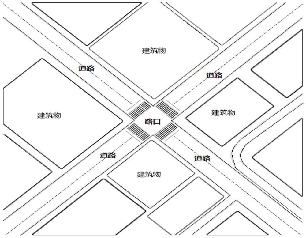
[0087] Select a common cross road intersection in an urban road, and the integrated video surveillance method for this large space area includes the following steps:

[0088] (1) Selection of areas to be monitored in large spaces

[0089] Select a rectangular area to be monitored in Baidu satellite map mode, or on the electronic map provided by other geographic information systems, and collect the coordinates of the four vertices of the area to be monitored from the electronic map, that is, the longitude corresponding to each vertex , latitude and altitude values, and its precision is in the "meter" level.

[0090] (2) Selection of video capture area

[0091] In the area to be monitored, select the range that requires real-time video monitoring for the place with moving targets as the video collection area; that is, determine the range that needs to use the camera to collect video streams in real time on the electronic map of the area to be monitored, usually people and vehic...


PUM


Abstract

The invention discloses an integral video monitoring method of a large space region. The integral video monitoring method of a large space region includes the following steps: selecting a rectangular region to be monitored on an electronic map, selecting a rectangular region having a motion object in the region to be monitored as the video acquisition region and the symbolic object, and drawing an AutoCAD planar graph; measuring the spatial position coordinates of the video acquisition region and each symbolic object; according to the spatial position coordinates, establishing three dimensional models; according to the range which can be monitored by cameras, dividing the video acquisition region into a plurality of video monitoring sections, after performing correction and gap filling process on the real-time video images acquired by each camera, respectively mapping the real-time video images to the three dimensional models of the corresponding video monitoring sections, and then generating a real time large space projection image of the region to be monitored by means of image gathering; and through a splicing screen, displaying and recording videos at the same time. The integral video monitoring method of a large space region realizes integral video monitoring of the large space region, and can provide complete global video data at the first time for dealing with emergent events.

Description

technical field [0001] The invention relates to a social security video monitoring system and a road traffic order management video monitoring system, in particular to an integrated video monitoring method for a large space area. Background technique [0002] The video surveillance system can bring the image flow information of the monitoring area to the observer. Because of its intuitiveness and real-time performance, it has been widely used in the fields of public safety, road traffic management, etc. powerful tool. [0003] However, in the video surveillance system, the cameras responsible for video information collection are in an independent working state, that is, each camera independently collects video information, and the video information is sent to the background monitoring room through a wired / wireless communication system and then displayed independently; a single camera is affected by its own perspective, Due to the constraints of parameters such as horizon, t...

Claims


Application Information

Patent Timeline
Patent Type & Authority Patents(China)
IPC IPC(8): G06T11/20G06T17/00G06T5/00G06F3/14H04N7/18
CPCG06F3/1423G06T5/005G06T5/006G06T11/206G06T17/00H04N7/18
Inventor 赵峰王珏李唯哲卞涧泉王志会黄守江
Owner ANHUI TIANSHENG INTELLIGENT TECH CO LTD
Learn More