A wireless sensor layout method for wind-induced vibration monitoring of bridges

A wireless sensor and wind-induced vibration technology, applied in design optimization/simulation, special data processing applications, geometric CAD, etc., can solve the problem of inability to accurately reflect the response characteristics of bridge wind-induced vibration, the inability to guarantee the connectivity of wireless sensor networks, and sensor data transmission Short distance and other issues, to achieve the effect of convenient wireless sensor layout, connectivity, and simple operation

Active Publication Date: 2020-06-16
HOHAI UNIV
View PDF4 Cites 1 Cited by
  • Summary
  • Abstract
  • Description
  • Claims
  • Application Information

AI Technical Summary

Problems solved by technology

However, the wind-induced vibration response of bridges is quite different from the vibration response under environmental excitation, and the measurement points selected based on the existing vibration sensor layout methods cannot accurately reflect the characteristics of the bridge wind-induced vibration response.
Secondly, the existing vibration sensor layout methods are all aimed at wired sensors, regardless of the distance between measuring points
For wireless sensors, due to the battery power supply, the data transmission distance of a single sensor is short, and the existing vibration sensor layout method cannot guarantee the connectivity of the wireless sensor network

Method used


Image

  • A wireless sensor layout method for wind-induced vibration monitoring of bridges
  • A wireless sensor layout method for wind-induced vibration monitoring of bridges
  • A wireless sensor layout method for wind-induced vibration monitoring of bridges

Examples


Embodiment

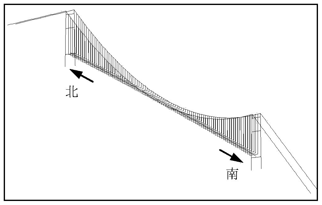
[0040] Such as figure 1 As shown, a wireless sensor deployment method for bridge wind-induced vibration monitoring in this embodiment includes the following steps:

[0041](1) Based on the design drawings of the bridge to be tested, the finite element model of the bridge to be tested is established using beam elements and rod elements. The positions of the optional measuring points of the bridge to be tested are consistent with the node positions of the finite element model, assuming that the total number of nodes in the finite element model is is M, then the number of optional measuring points for wind-induced vibration monitoring of the bridge under test is also M;

[0042] (2) According to the geographical location of the bridge to be tested and the bridge design code, select the wind spectrum model for the design of the bridge, and use the harmonic superposition method to simulate the wind field of the bridge site area under test. The length of the wind field sample is N;...


PUM


Abstract

The invention provides a wireless sensor placement method for wind-induced bridge vibration monitoring. The method comprises the following steps of: firstly simulating a wind field on the basis of a bridge finite element model and a standard wind spectrum, and carrying out calculation to obtain a wind-induced bridge vibration response by adoption of a wind-induced bridge vibration response time domain calculation method; calculating a contribution degree, for the wind-induced bridge vibration, of each selectable measurement point, drawing a contribution degree curve of each selectable measurement point, and arranging wireless sensors by taking peak points and valley points of the contribute degree curves as key measurement points; and further uniformly arranging relay measurement points as few as possible between the key measurement points and between the key measurement points and a data aggregation node of a data processing center, so as to realize the wireless sensor placement of wind-induced bridge vibration monitoring. The method has the advantages of being simple to operate and easy to realize, has the effect of improving the representativeness of sensor data acquisition and the reliability of transmission, and has a wide engineering application prospect.

Description

technical field [0001] The invention belongs to the fields of civil engineering and bridge monitoring, and in particular relates to a wireless sensor laying method for wind-induced vibration monitoring of bridges. Background technique [0002] A bridge is a key node of a modern transportation system, an inseparable and important component of a country's infrastructure, and an indispensable and important support for a country's economic development. In order to meet the regional economic development and transportation needs, a large number of kilometer-level cable-supported bridges have been built and put into use all over the country, such as Beipanjiang Bridge, Sutong Bridge, Runyang Bridge, Hangzhou Bay Bridge, Xihoumen Bridge, etc. . These bridges have the characteristics of large span, flexible structure, high tower and light weight, and the vibration response under wind load becomes one of the main factors affecting driving comfort and structural safety. Not only that...

Claims


Application Information

Patent Timeline
Patent Type & Authority Patents(China)
IPC IPC(8): G06F30/18G06F30/23
CPCG06F30/18G06F30/23
Inventor 周广东谢美希朱太勇
Owner HOHAI UNIV
Why Eureka
Try Eureka