Imaging display method and apparatus capable of achieving monocular 3D effect, and application parameter thereof
A 3D effect and display method technology, applied in the field of 3D display, can solve the problems of incoordination of focal length and inability to realize monocular 3D imaging, etc., to achieve the effect of solving human eye discomfort or dizziness and improving immersion
- Summary
- Abstract
- Description
- Claims
- Application Information
AI Technical Summary
Problems solved by technology
Method used
Image
Examples
Embodiment 1
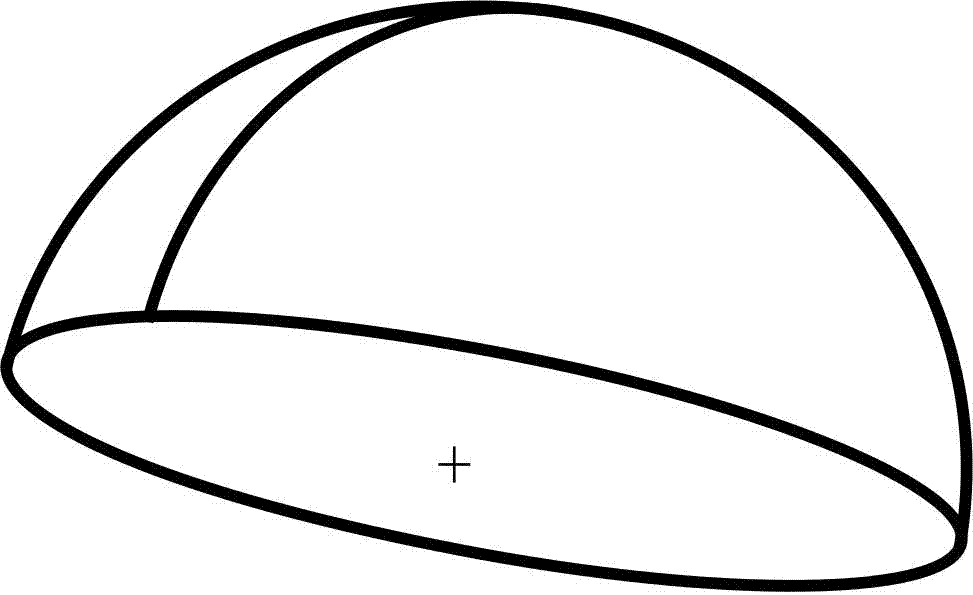
[0034] Embodiment 1 of the present invention provides a single-eye 3D imaging display method, in which the image of the panel screen is demonstrated on the arc display surface following a parallel projection method.
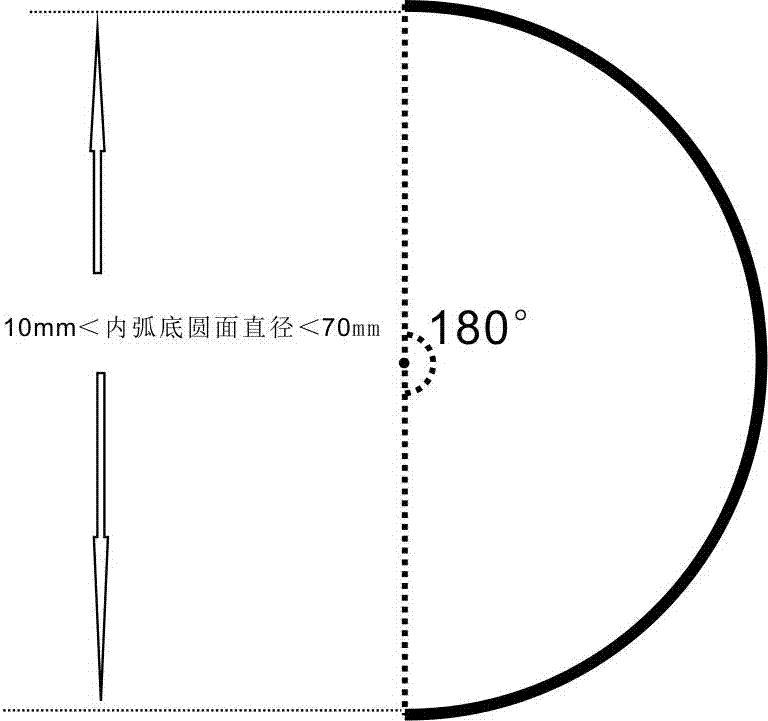
[0035] Specifically, on the arc display surface, the pixel position of the panel screen image is demonstrated on the inner arc surface by means of optical refraction, optical fiber image guide or direct construction of an inner arc display screen on the panel screen image according to the rules of the parallel projection method. The relative positional relationship between the pixels of the panel screen image and the image pixels on the inner arc surface is, the radius of the pixel ring on the panel screen is r, and the radius of the arc display surface is R, then the pixel point and the inner arc surface vertex The distance on the inner arc surface is: 2πR*{arc sin (r / R)} / 360°. Similarly, on the same section, the distance between the center point of the screen an...
Embodiment 2
[0037] Embodiment 2 of the present invention also provides a monocular 3D effect imaging display method, which can also be demonstrated directly by comparing the visible range of the wearing device with the visible range of the experience scene in the application, without calculating the image projection stretch ratio.
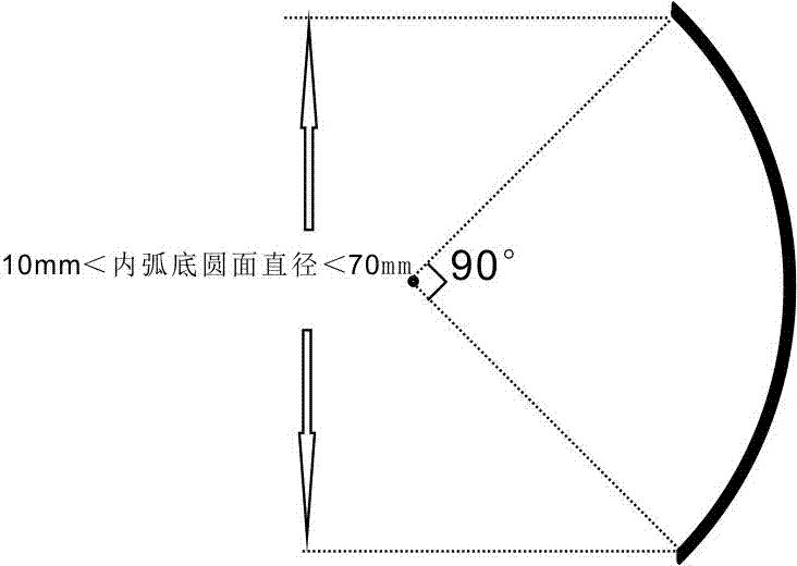
[0038]First of all, it is necessary to determine the visible range of the device. When the device is worn, the angle between the display edge and the line of sight axis in the head-up state at the center of the pupil determines the visible range of the device (the included angle is generally not greater than 90°, and the total viewing angle is not greater than 180° °).
[0039] At the same time, it is necessary to determine the visible range of the scene. The visible range of photos and movies is determined by the maximum wide-angle value of the shooting equipment (generally not greater than 170°). The visible range of virtual data scenes is generally unlimited...
Embodiment 3
[0043] Figure 6 The application mode of the imaging and display device for monocular 3D effect provided by Embodiment 3 of the present invention in binocular 3D glasses is shown.
[0044] In the application of the imaging inner arc surface display technology of the monocular 3D effect, in the application of binocular use, the visual center point and the focal point of the image can be changed by physically rotating the lens or through the numerical control adjustment of the image playback control system. The specific angle of rotation is determined by the interpupillary distance P and depth of field D are jointly determined, and the optimal parameter of the rotation angle is: arc tan (P / 2D).
PUM
 Abstract
Description
Claims
Application Information
 - R&D
- Intellectual Property
- Life Sciences
- Materials
- Tech Scout
- Unparalleled Data Quality
- Higher Quality Content
- 60% Fewer Hallucinations
Browse by: Latest US Patents, China's latest patents, Technical Efficacy Thesaurus, Application Domain, Technology Topic, Popular Technical Reports.
© 2025 PatSnap. All rights reserved.Legal|Privacy policy|Modern Slavery Act Transparency Statement|Sitemap|About US| Contact US: help@patsnap.com


