
Anode guide rod assembly and manufacturing method thereof

A technology of an anode guide rod and a manufacturing method, which is applied in the field of aluminum smelting, can solve the problems of cracking of explosive discs, large maintenance amount, and high maintenance cost, and achieve the effects of tighter and firmer connections, improved production yield, and reduced inspection personnel

Active Publication Date: 2017-08-18
LUXCASE PRECISION TECH (YANCHENG) CO LTD
View PDF3 Cites 0 Cited by
  • Summary
  • Abstract
  • Description
  • Claims
  • Application Information

AI Technical Summary

Problems solved by technology

[0005] 1. High production cost, that is, explosive discs, power consumption, welding equipment, aluminum welding wire, etc.;
[0006] 2. The labor cost is high, that is, grinding and polishing are required. Electric welders and argon-fluorine welders are special types of work with high technical content and high wages;
[0007] 3. The maintenance cost is high and the maintenance volume is large, that is, the cost of cracking and replacing explosive discs, and the cost of welding cracks in aluminum-aluminum welding;
[0008] 4. Occupational hazards are high, that is, more dust, noise, harmful gases and radiation are generated;
[0009] 5. The output is low and the scrap rate is high, that is, it takes one person two hours to complete a set of guide rods, and the high temperature of welding can easily cause the explosive disc to crack and cause waste;
[0011] 7. The anode guide rod assembly in the prior art still has the defect of high energy consumption (that is, high power consumption) in the production process

Method used


Image

  • Anode guide rod assembly and manufacturing method thereof
  • Anode guide rod assembly and manufacturing method thereof
  • Anode guide rod assembly and manufacturing method thereof

Examples


Embodiment Construction

[0055] The principles and features of the present invention are described below in conjunction with the accompanying drawings, and the examples given are only used to explain the present invention, and are not intended to limit the scope of the present invention.

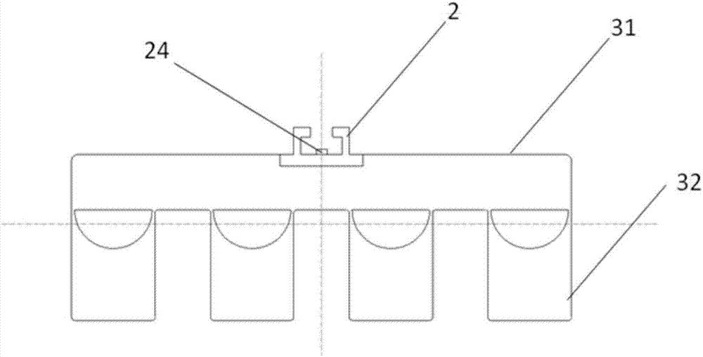
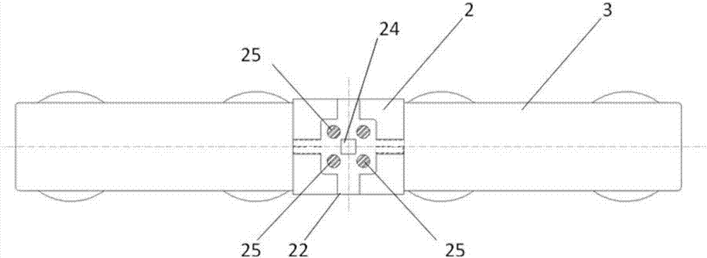
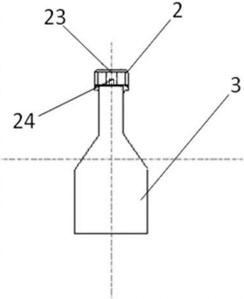
[0056] Such as Figure 1-7 As shown, an anode guide rod assembly includes an anode guide rod 1, a connector 2 and a steel claw assembly 3; the bottom of the connector 2 is fixedly connected to the upper part of the steel claw assembly 3, and the fixed connection method can be that the connector 2 It is integrally cast with the steel claw assembly 3, and the connecting piece 2 and the steel claw assembly 3 can also be welded together; It is located in the trough structure 21 and connected with the trough structure 21 by casting. In specific use, the connecting piece 2 can be made of steel; the anode guide rod 1 is an aluminum anode guide rod; the casting solution used during casting can be aluminum solution. In a s...


PUM


Abstract

The invention provides an anode guide rod assembly and a manufacturing method thereof. The anode guide rod assembly comprises an anode guide rod, a connecting piece and a steel jaw assembly, wherein the bottom of the connecting piece is fixedly connected with the upper part of the steel jaw assembly; the connecting piece is of a groove-shaped structure; the bottom of the anode guide rod is in the groove-shaped structure; and the bottom of the anode guide rod and the groove-shaped structure are connected through casting. The manufacturing method of the anode guide rod assembly comprises the steps of fixedly connecting the bottom of the connecting piece with the upper part of the steel jaw assembly; putting the bottom of the anode guide rod into the groove-shaped structure of the connecting piece; and connecting the anode guide rod with the connecting piece through casting. The anode guide rod assembly and the manufacturing method thereof have the advantages that connection is tighter and firmer, production efficiency is high, labor cost is low, production cost is reduced, maintenance amount basically is zero, pollution is avoided, and energy conservation and consumption reduction are achieved.

Description

technical field [0001] The invention belongs to the technical field of aluminum smelting, and in particular relates to an anode guide rod assembly and a manufacturing method thereof. Background technique [0002] Aluminum is the most widely used non-ferrous metal material. The modern aluminum industry generally adopts the cryolite-alumina molten salt electrolysis method to produce, and the direct current is introduced by the steel claw of the anode guide rod, and the carbon material connected with the steel claw of the anode guide rod is consumed. The anode block produces molten aluminum under the action of the cathode, and the molten aluminum is cast into aluminum ingots, profiles, etc. The extensive use of anodes makes the consumption of anodes in aluminum electrolysis a cost that cannot be ignored for aluminum products, and it is also an important hidden energy consumption in the process of electrolytic aluminum. Anode blocks for aluminum are known as the "heart of elect...

Claims


Application Information

Patent Timeline
IPC IPC(8): C25C3/12B22D19/04
CPCB22D19/04C25C3/12
Inventor 宁俊傑宁亚军
Owner LUXCASE PRECISION TECH (YANCHENG) CO LTD
Learn More